
Elevator system having drive motor located below the elevator car

Inactive Publication Date: 2005-03-01
OTIS ELEVATOR CO
View PDF62 Cites 39 Cited by
  • Summary
  • Abstract
  • Description
  • Claims
  • Application Information

AI Technical Summary

Benefits of technology

An advantage of the present invention is that the elevator system significantly reduces the space and construction costs compared with an elevator system having a machine room.
is that the elevator system significantly reduces the space and construction costs compared with an elevator system having a machine room.
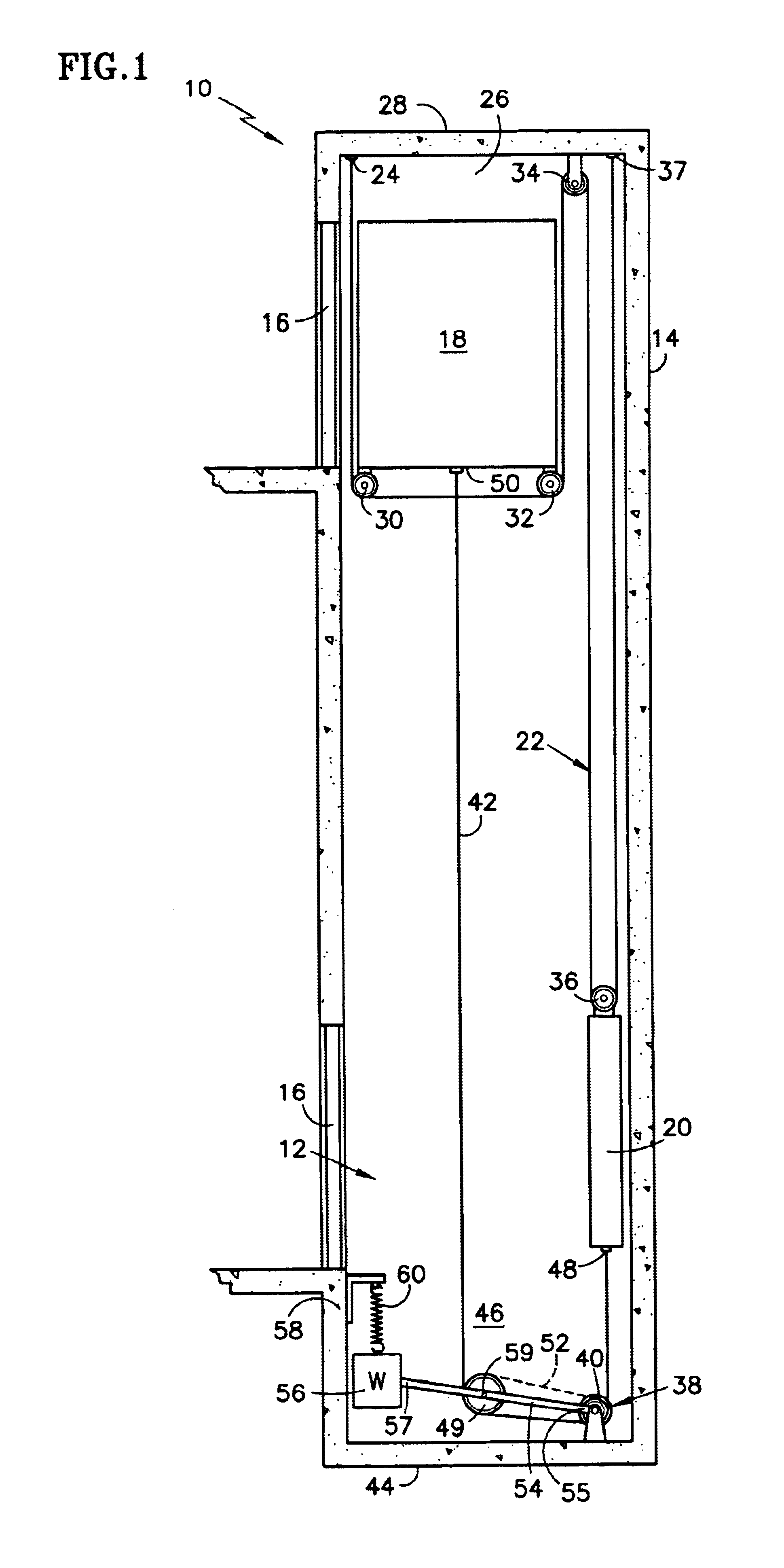
A second advantage of the present invention is that the hoistway dimensions can be kept to a minimum because the drive motor does not encroach into the hoistway space between the elevator car and a sidewall of the hoistway.
A third advantage of the present invention is simplified and safe access to the drive motor and associated equipment from the elevator pit.
A fourth advantage of the present invention is that flat rope technology reduces the size of the drive motor and sheaves, and thereby reduces the pit space required for accommodating the motor and sheaves.

Problems solved by technology

Considerable expense is involved in the construction of a machine room for an elevator.
The expense includes the cost of constructing the machine room, the structure required to support the weight of the machine room and elevator equipment, and the cost of shading adjacent properties from sunlight (e.g., sunshine laws in Japan and elsewhere).
These elevator systems are difficult to install and maintain because hoistway access can be difficult or dangerous especially to maintenance people while working in the hoistway on machinery that controls elevator motion if the machinery, such as the drive motor, is located in a space between the elevator car and a sidewall of the hoistway.
Furthermore, elevator systems typically require additional hoistway space to accommodate machinery disposed between the car and sidewall of the hoistway.

Method used


Image

  • Elevator system having drive motor located below the elevator car
  • Elevator system having drive motor located below the elevator car
  • Elevator system having drive motor located below the elevator car

Examples


Embodiment Construction

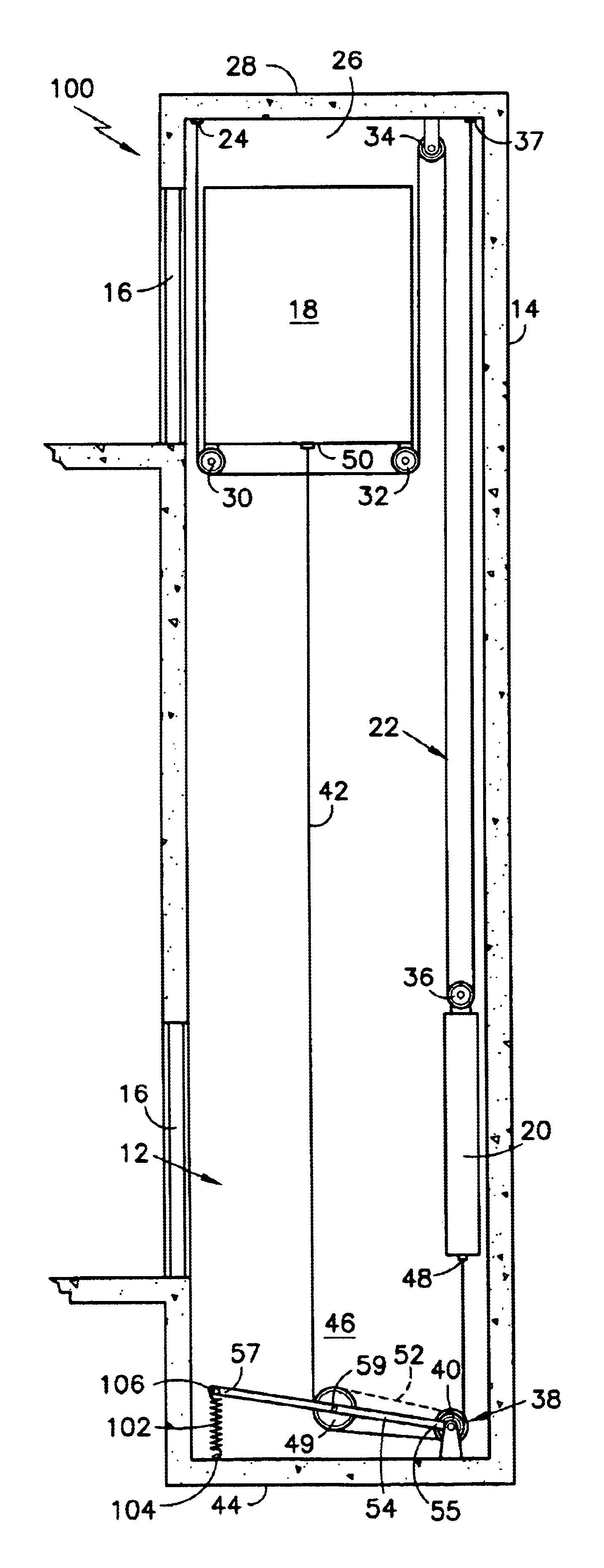
Referring to FIG. 1, an elevator system embodying the present invention is generally designated by the reference number 10. The elevator system 10 includes a hoistway 12 defined by a surrounding structure 14, such as a building. The hoistway 12 includes door openings at each level along the hoistway for accepting hoistway doors 16, 16. An elevator car 18 is provided in the hoistway 12 for upward and downward movement along the hoistway via conventional elevator guide rails (not shown). A counterweight 20 movably coupled to conventional counterweight guide rails (not shown) is located at a side of the hoistway 12 in a space extending along the length of the hoistway between the elevator car 18 and the sidewall 14 of the hoistway for balancing the elevator car during its upward and downward movement along the hoistway.

The elevator system 10 includes at least one flat, suspension rope or belt 22 for supporting the weight of the elevator car 18 and the counterweight 20. The suspension r...


PUM


Abstract

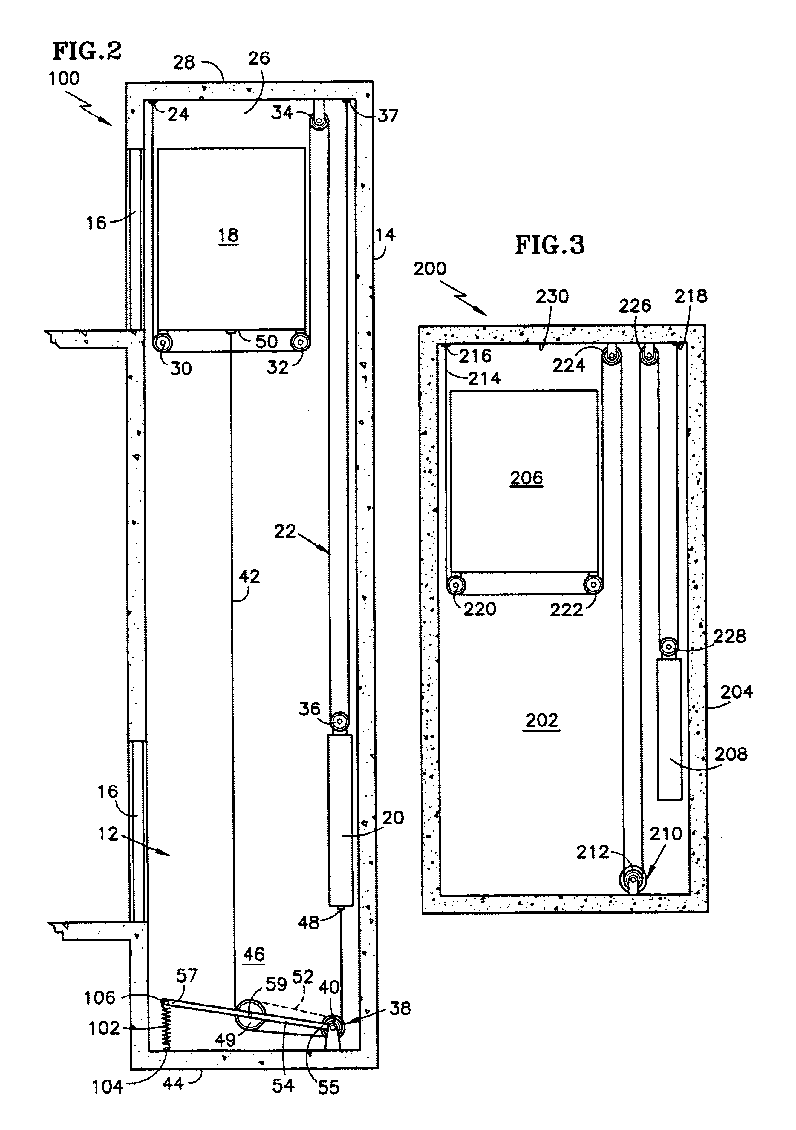
An elevator system includes an elevator hoistway defined in a surrounding structure, such as a building. An elevator car and counterweight are located in the hoistway. A drive motor and associated drive sheave are disposed at a bottom portion of the hoistway. The drive motor is coupled to the elevator car and the counterweight via at least one flat rope for moving the elevator car upwardly and downwardly along the hoistway.

Description

FIELD OF THE INVENTIONThe present invention relates generally to an elevator system, and more particularly to an elevator system including a drive motor located in the hoistway below the elevator car.BACKGROUND OF THE INVENTIONConsiderable expense is involved in the construction of a machine room for an elevator. The expense includes the cost of constructing the machine room, the structure required to support the weight of the machine room and elevator equipment, and the cost of shading adjacent properties from sunlight (e.g., sunshine laws in Japan and elsewhere).Elevator systems have been developed to avoid the expense of a machine room. These elevator systems are difficult to install and maintain because hoistway access can be difficult or dangerous especially to maintenance people while working in the hoistway on machinery that controls elevator motion if the machinery, such as the drive motor, is located in a space between the elevator car and a sidewall of the hoistway. Furthe...

Claims


Application Information

Patent Timeline
IPC IPC(8): B66B7/06B66B7/10B66B11/00
CPCB66B11/008B66B7/10
Inventor ERICSON, RICHARD J.
Owner OTIS ELEVATOR CO
Learn More