Surgical handpiece

a handpiece and hand technology, applied in the field of cataract surgery, can solve the problems of difficult temperature control of heated solutions and deteriorating vision

Inactive Publication Date: 2005-03-01
ALCON RES LTD
View PDF60 Cites 103 Cited by
  • Summary
  • Abstract
  • Description
  • Claims
  • Application Information

AI Technical Summary

Problems solved by technology

When age or disease causes the lens to become less transparent, vision deteriorates because of the diminished light which can be transmitted to the retina.
Temperature control of the heated solution can be difficult because the fluid tubings feeding the handpiece typically are up to two meters long, and the heated solution can cool considerably as it travels down the length of the tubing.

Method used


Image

  • Surgical handpiece
  • Surgical handpiece
  • Surgical handpiece

Examples


Embodiment Construction

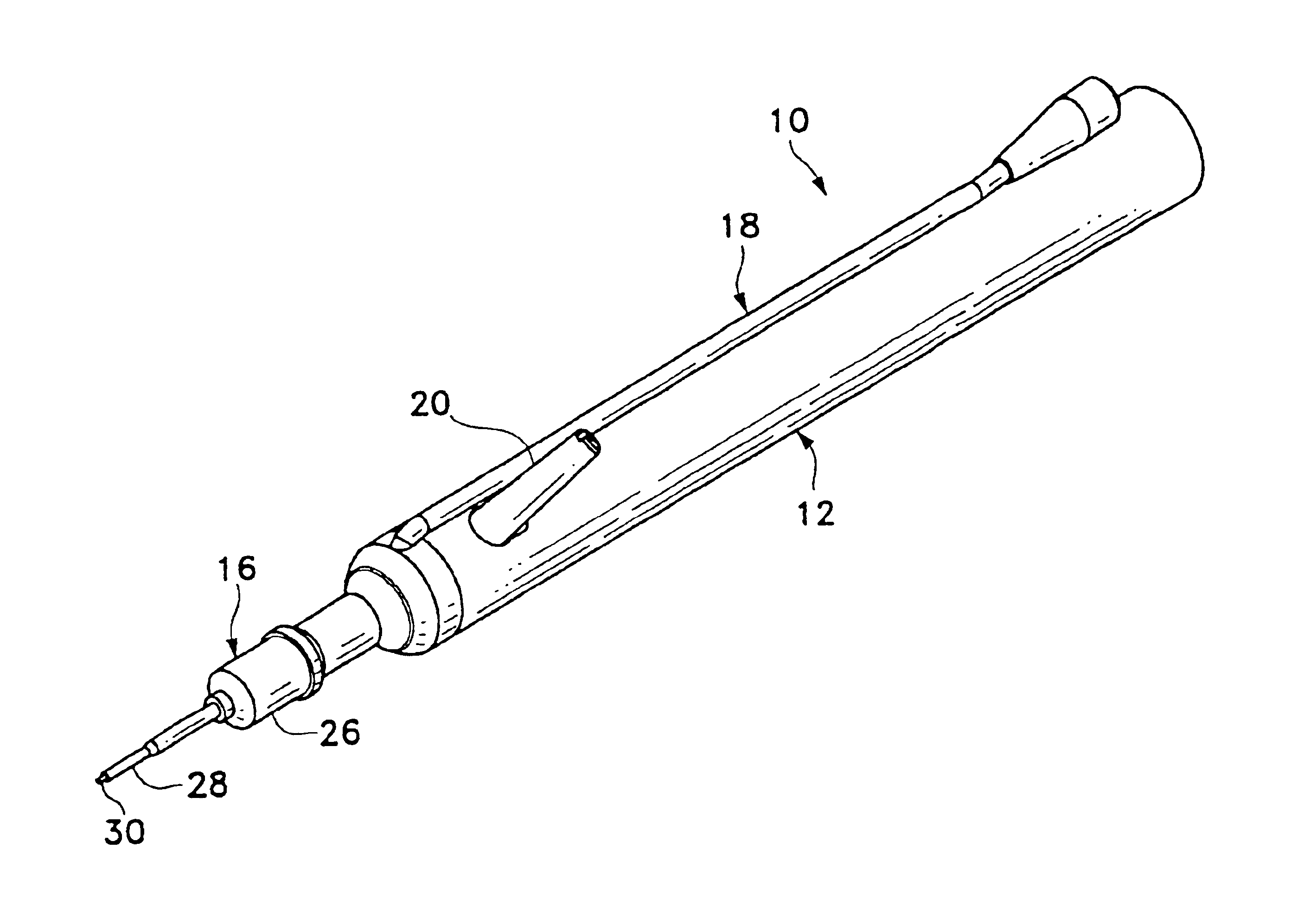
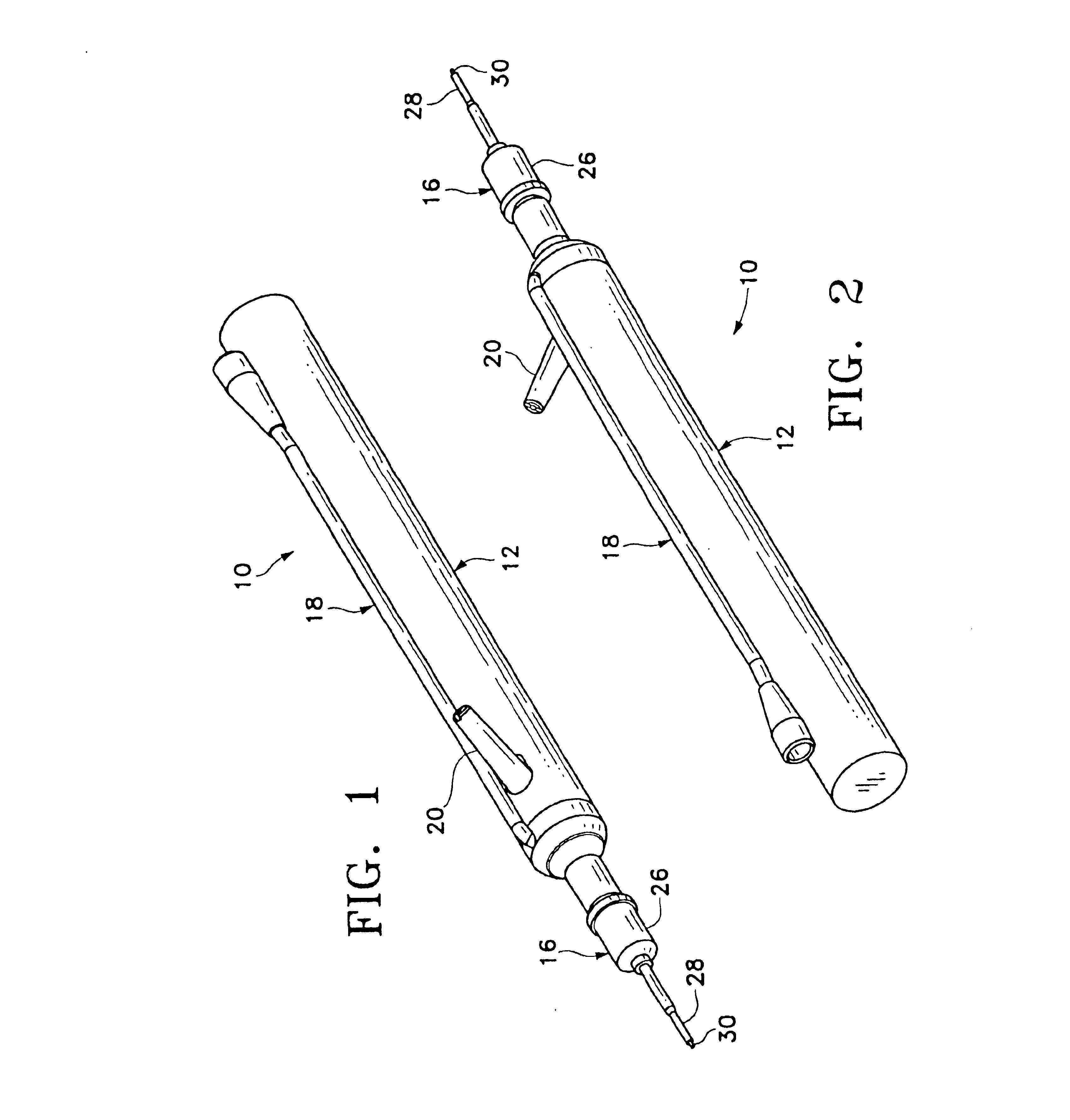
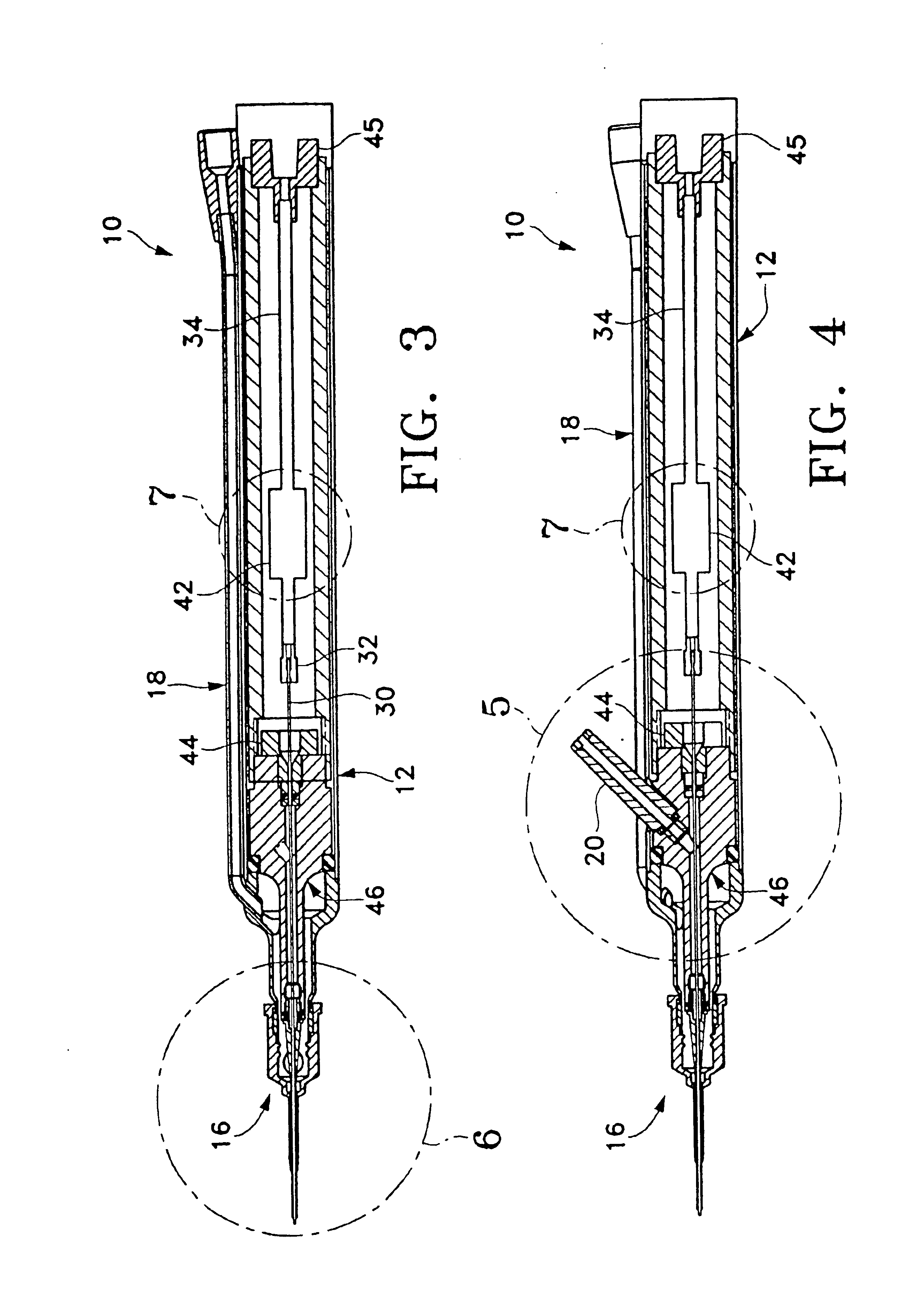
Handpiece 10 of the present invention generally includes handpiece body 12 and operative tip 16. Body 12 generally includes external irrigation tube 18 and aspiration fitting 20. Body 12 is similar in construction to well-known in the art phacoemulsification handpieces and may be made from plastic, titanium or stainless steel. As best seen in FIG. 6, operative tip 16 includes tip / cap sleeve 26, needle 28 and tube 30. Sleeve 26 may be any suitable commercially available phacoemulsification tip / cap sleeve or sleeve 26 may be incorporated into other tubes as a multi-lumen tube. Needle 28 may be any commercially available hollow phacoemulsification cutting tip, such as the TURBOSONICS tip available from Alcon Laboratories, Inc., Fort Worth, Tex. Tube 30 may be any suitably sized tube to fit within needle 28, for example 29 gauge hypodermic needle tubing.

As best seen in FIG. 5, tube 30 is free on the distal end and connected to pumping chamber 42 on the proximal end. Tube 30 and pumping ...


PUM


Abstract

A surgical handpiece having at least two lumens or tubes mounted to a body. At least one tube is used for aspiration and at least one other tube is used to inject heated surgical fluid for liquefying a cataractous lens. A portion of the second tube is enlarged to form a pumping chamber. The pumping chamber works by boiling a small volume of the surgical fluid. As the fluid boils, it expands rapidly, thereby propelling the liquid downstream of the pumping chamber out of the second tube. The pumping chamber may use a pair of electrodes.

Description

BACKGROUND OF THE INVENTIONThis invention relates generally to the field of cataract surgery and more particularly to a pumping chamber for a handpiece for practicing the liquefracture technique of cataract removal.The human eye in its simplest terms functions to provide vision by transmitting light through a clear outer portion called the cornea, and focusing the image by way of the lens onto the retina. The quality of the focused image depends on many factors including the size and shape of the eye, and the transparency of the cornea and lens.When age or disease causes the lens to become less transparent, vision deteriorates because of the diminished light which can be transmitted to the retina. This deficiency in the lens of the eye is medically known as a cataract. An accepted treatment for this condition is surgical removal of the lens and replacement of the lens function by an artificial intraocular lens (IOL).In the United States, the majority of cataractous lenses are remove...

Claims


Application Information

Patent Timeline
Patent Type & Authority Patents(United States)
IPC IPC(8): A61F9/007A61B17/32A61B18/04A61M1/00
CPCA61F9/00736A61B17/3203A61B2017/320084A61B2018/044A61M1/0058A61F9/00745A61F9/00763A61B2018/046A61M1/77
Inventor SUSSMAN, GLENNCOHEN, DONALD M.
Owner ALCON RES LTD
Why Eureka
Try Eureka