
Coating wear indicator

a technology of coating wear indicator and coating layer, which is applied in the direction of transportation and packaging, synthetic resin layered products, and radiation-absorbing paints. it can solve the problems of affecting the appearance of the coating

Inactive Publication Date: 2005-03-01
ZEP IP HLDG LLC
View PDF21 Cites 53 Cited by
  • Summary
  • Abstract
  • Description
  • Claims
  • Application Information

AI Technical Summary

Problems solved by technology

These coatings can wear over time and lose the ability to protect the substrate from damage from, for example, U.V. light.
Also, these coatings may be clear and thus make it difficult to visually determine if the coating is still protecting the substrate.

Method used


Image

  • Coating wear indicator
  • Coating wear indicator
  • Coating wear indicator

Examples


examples

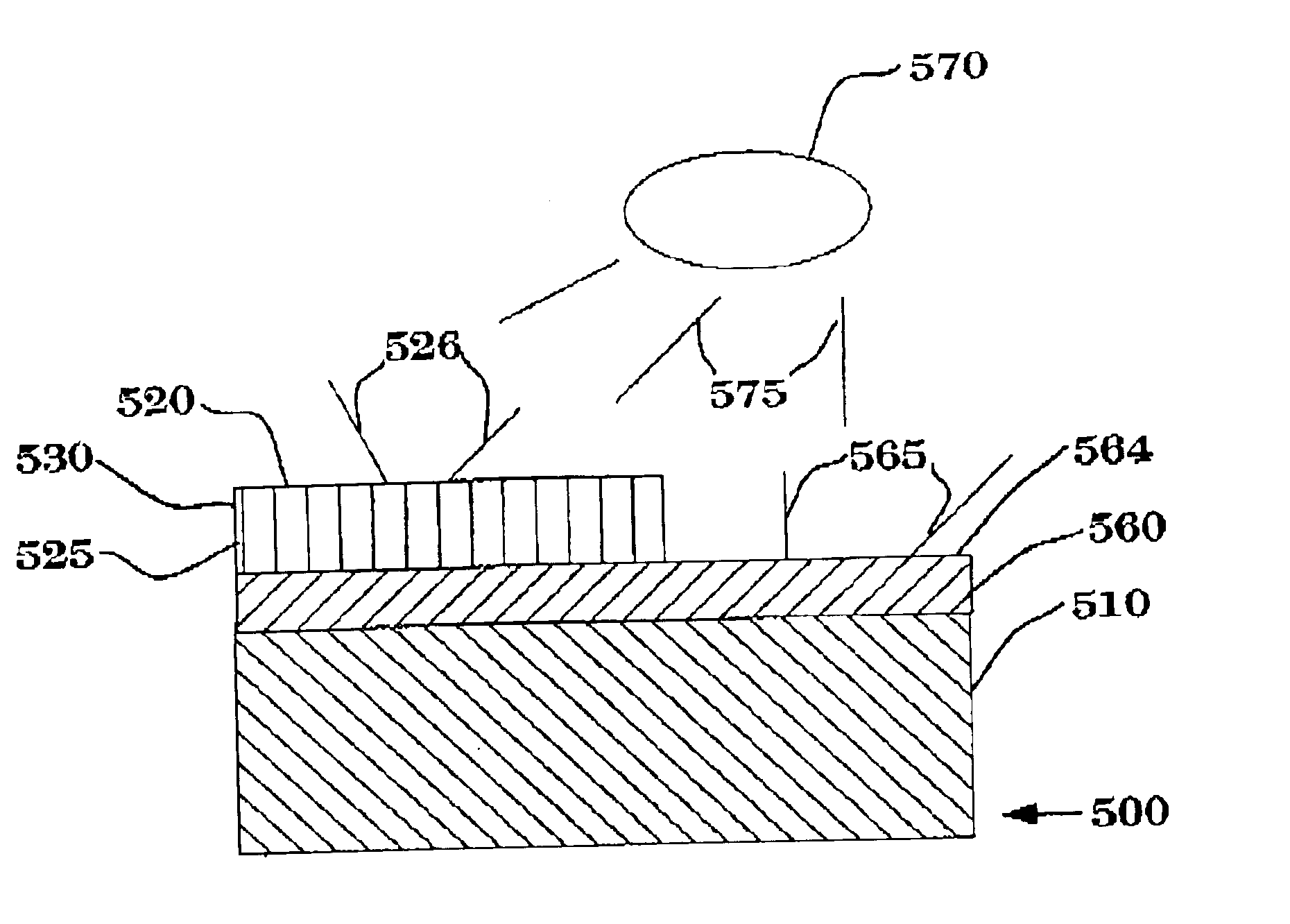
A water soluble U.V. sensitive dye CO98-012 Inv Ink w / B N / P Yellow (available from UV Process Supply Inc. Chicago Ill.) was applied to a ceramic tile spelling the phraseWAX ME”. The U.V. sensitive dye was allowed to dry and two coats of a sealing layer of Gemstar Laser was sprayed on the U.V. sensitive dye. A coating of Padlock coating containing an optical brightener Tinapol that also absorbs light in the U.V. range was applied to the tile covering the “W” and “M”, and allowed to dry. When U.V. light source was applied to the tile the “AX” and “E” glowed in a bright green color and the remaining portions of the tile covered by the Padlock coating with optical brightener glowed in a bright blue color. The letters under the Padlock coated half did not glow green.


PUM

PropertyMeasurementUnit
thicknessaaaaaaaaaa
thicknessaaaaaaaaaa
thicknessaaaaaaaaaa

Abstract

A coating composition includes a material adapted to form a coating; and a material that fluoresces when exposed to U.V. light or the material adapted to form a coating contains a U.V. blocker disposed on a U.V. indicator. A kit containing a U.V. indicator and material adapted to form a coating containing a U.V. blocker. Methods of coating a substrate with the coating compositions are also disclosed.

Description

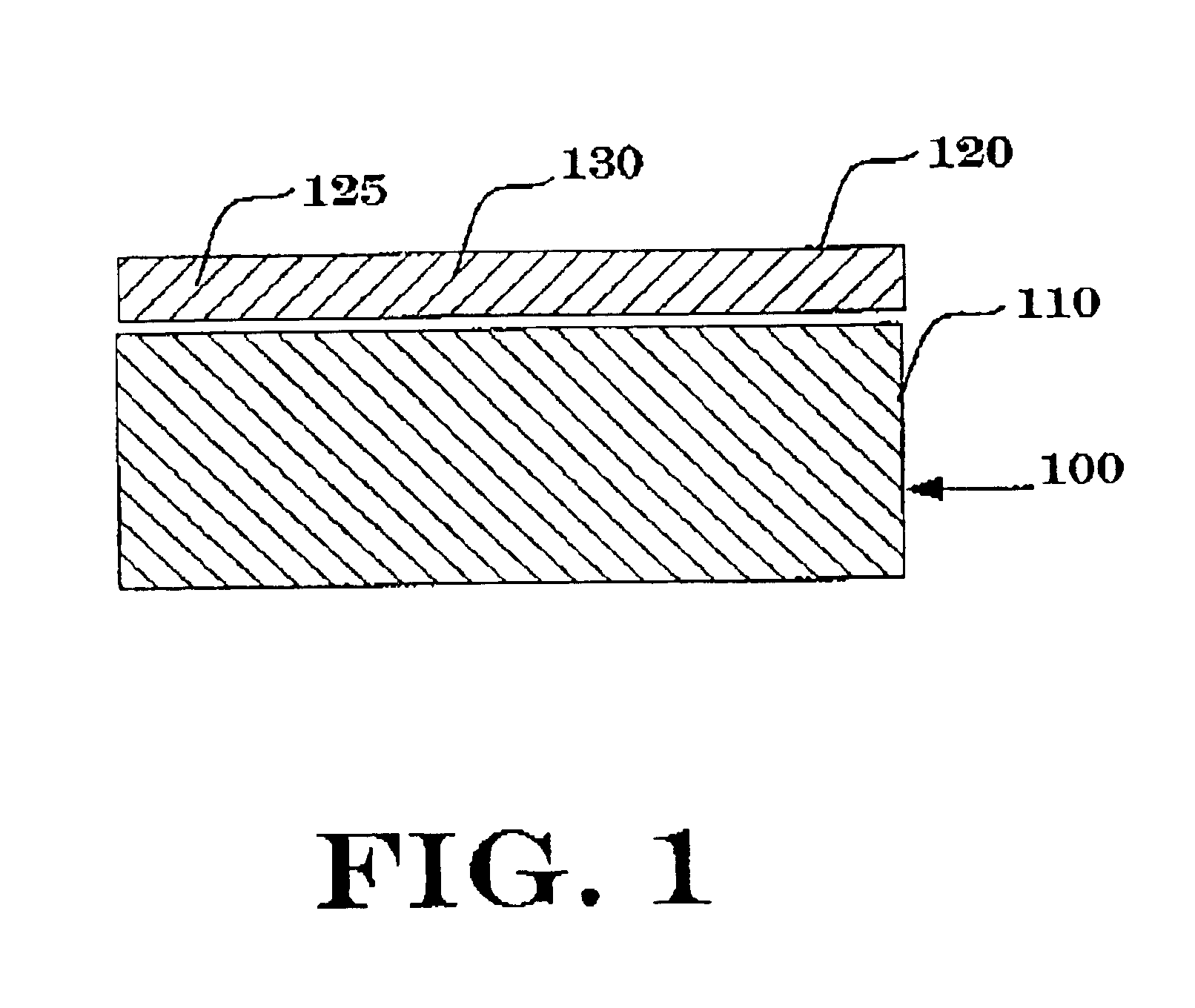
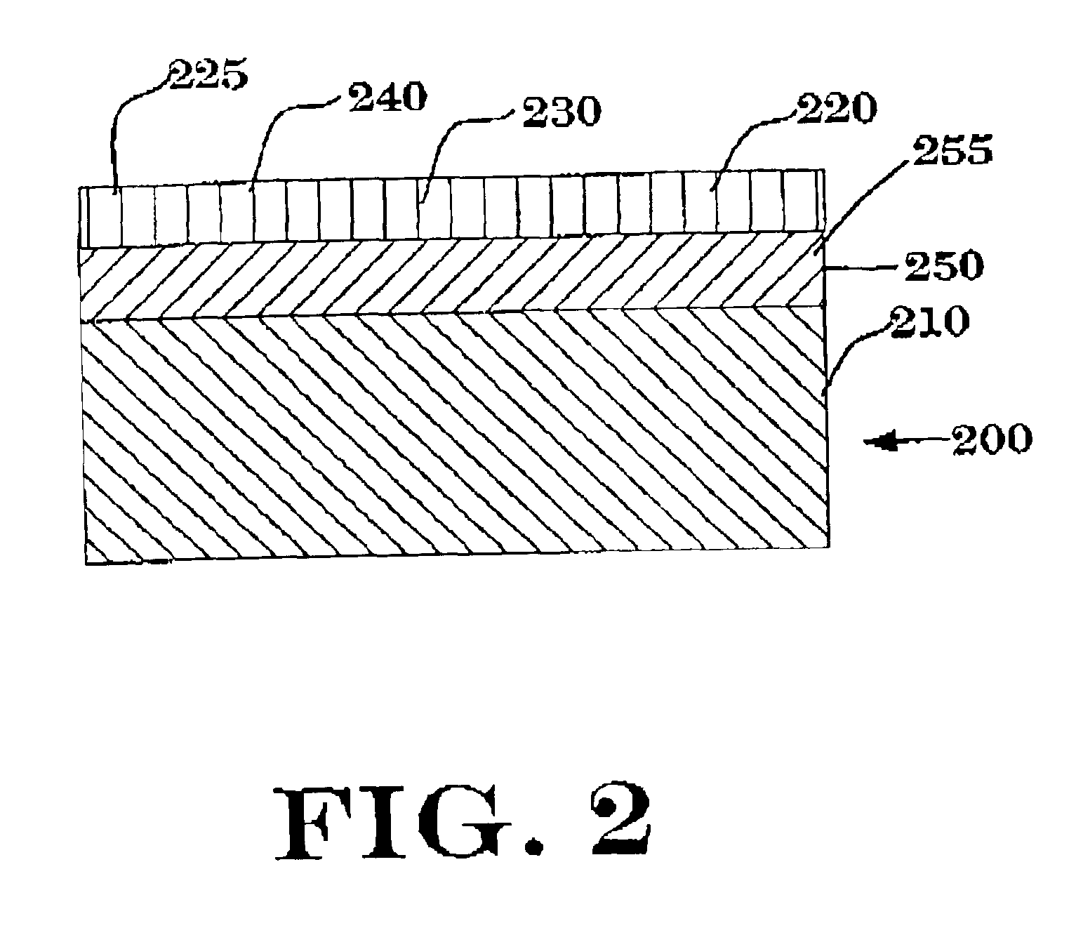
BACKGROUND OF THE INVENTIONThe invention relates to compositions, coated substrates and method that indicate a coating is worn and no longer protecting the substrate.Coating disposed on substrates may contain components that protect the substrate from damage, for example, from U.V. light. These coatings can wear over time and lose the ability to protect the substrate from damage from, for example, U.V. light. Also, these coatings may be clear and thus make it difficult to visually determine if the coating is still protecting the substrate.Given the foregoing, there is a need to provide coating compositions that can indicate when a coating is worn and no longer protecting the substrate.BRIEF DESCRIPTION OF THE FIGURESFIG. 1 is a cross-sectional view of a coated substrate in accordance with an embodiment of the invention.FIG. 2 is a cross-sectional view of a coated substrate in accordance with another embodiment of the invention.FIG. 3 is a cross-sectional view of a coated substrate i...

Claims


Application Information

Patent Timeline
Patent Type & Authority Patents(United States)
IPC IPC(8): B05D7/00C09D7/00B05D5/06
CPCB05D7/584C09D7/00B05D5/06B05D5/061Y10T428/12014Y10T428/25Y10T428/24942Y10T428/31855Y10T428/31678
Inventor OLSON, KEITHMATTIA, PAUL
Owner ZEP IP HLDG LLC
Learn More