2-stage large bandwidth amplifier using diodes in the parallel feedback structure

a large bandwidth, diode technology, applied in amplifiers with impedence circuits, amplifiers with semiconductor devices/discharge tubes, amplifiers with only semiconductor devices, etc., can solve the problems of limited amplifier b>10/b> overall bandwidth, unstable amplifier b>10/b>, and imposed bandwidth and gain constraints on amplifiers. , to achieve the effect of expanding the output transistor q2 bandwidth and the overall amplifier bandwidth

Inactive Publication Date: 2005-03-01
IBM CORP
View PDF4 Cites 4 Cited by
  • Summary
  • Abstract
  • Description
  • Claims
  • Application Information

AI Technical Summary

Benefits of technology

It is therefore a primary object of the present invention to provide an improved 2-stage large bandwidth amplifier with diodes in the parallel feedback structure that significantly extends the output transistor Q2 bandwidth, and thus the overall amplifier bandwidth.

Problems solved by technology

As a result, bandwidth and gain constraints are imposed to the amplification circuits on the receiving side of these high speed transmission systems.
Nevertheless, the overall bandwidth of amplifier 10 is still limited by the second stage, i.e. Output transistor Q2, because the collector capacitance of transistor Q2 remains large.
Finally, amplifier 10 is often unstable, because the gain of feedback structure 13 is quite often greater than 1.

Method used


Image

  • 2-stage large bandwidth amplifier using diodes in the parallel feedback structure
  • 2-stage large bandwidth amplifier using diodes in the parallel feedback structure
  • 2-stage large bandwidth amplifier using diodes in the parallel feedback structure

Examples


Embodiment Construction

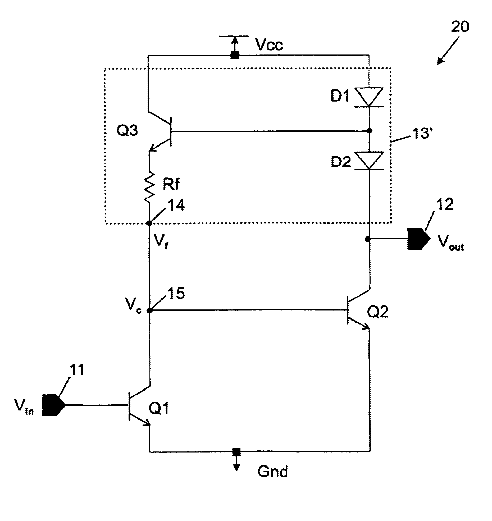
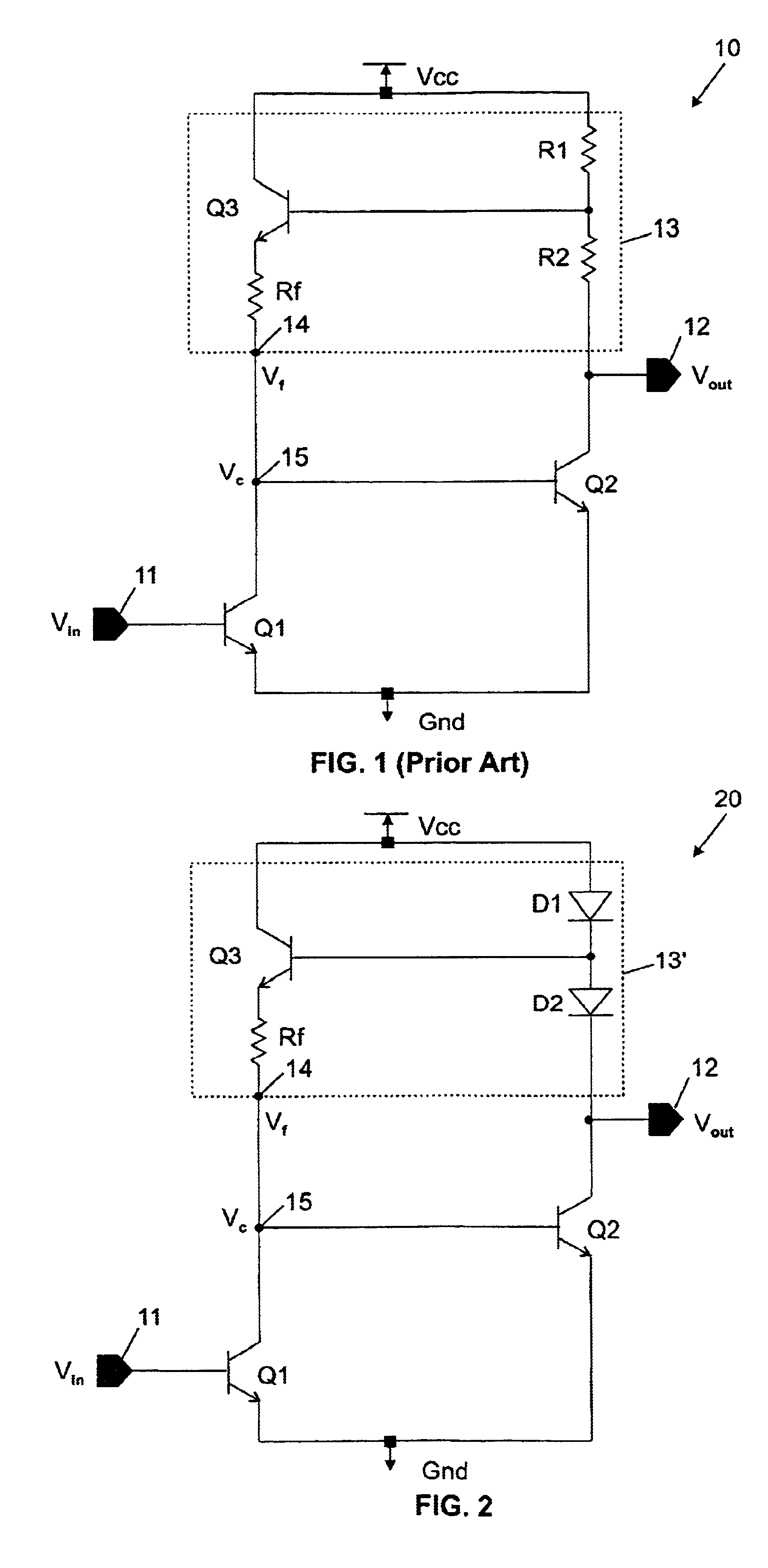
According to the teachings of the present invention, the amplifier shown in FIG. 1 is improved by reducing the collector capacitance of the output transistor Q2 and getting substantially identical bandwidth for each stage. Now turning to FIG. 2, where the improved amplifier circuit is referenced 20, these objectives are met by replacing the two resistors R1 and R2 by two diode-connected bipolar devices labeled D1 and D2, which can be identical devices. Surprisingly, these diodes D1 and D2 which are not linear elements, perform better than resistors that are perfectly linear. The lower resistance that is presented by the two diodes D1 and D2 also reveals to be a valuable contribution to the expected results. This construction minimizes the capacitance loading on the collector of transistor Q2 and improves the bandwidth of the second stage. The common node between the two diodes is used as the intermediate tap of the resistor divider to still bias transistor Q3 base. But, the feedback...


PUM


Abstract

There is disclosed an improved 2-stage large bandwidth amplifier (20) comprised of two stages formed by first and second bipolar transistors (Q1,Q2) configured in common emitter that are connected in series with their emitters connected to a first supply voltage (Gnd). The input signal (Vin) is applied to the base of said first transistor via an input terminal (11), while the output signal (Vout) is available at an output terminal (12) connected to the collector of said second transistor. A parallel feedback structure (13′) is provided. It consists, in a first branch, of two diodes (D1,D2) in series connected between a second supply voltage (Vcc) and the collector of the second bipolar transistor, and in another branch of a third bipolar transistor (Q3) configured in emitter follower with a resistor (Rf) in the emitter. The base and the collector of said third bipolar transistor are respectively connected to the common node of said diodes and to said second supply voltage. The resistor is connected to the common node of said first and second transistors to inject the feedback signal (Vf). Because, the two bodies have a low internal resistance and reduce the collector capacitance of the second transistor, the overall bandwidth of the improved amplifier is significantly extended in the very high frequencies (e.g. 20 GHz and above).

Description

BACKGROUND OF INVENTIONThe present invention relates to high speed transmission systems and more particularly to an improved 2-stage large bandwidth amplifier with diodes in the parallel feedback structure.In high speed transmission systems such as those involved in the forthcoming 10 Gb / s Ethernet, the signal after transmission along a media is largely attenuated and needs to be amplified before any operation is performed in the receiving section (A / D conversion, clock synchronization, data serialization, . . . etc.). The amplification circuits of these systems must work at the highest possible speed because bits are serialized in the emitting section before they are sent on a single transmission channel. As a result, bandwidth and gain constraints are imposed to the amplification circuits on the receiving side of these high speed transmission systems.Conventional amplification solutions are based on bipolar devices that are superior to MOSFET devices because of their higher Ft (tr...

Claims


Application Information

Patent Timeline
Patent Type & Authority Patents(United States)
IPC IPC(8): H03F3/343
CPCH03F3/3432H03F3/343
Inventor GABILLARD, BERTRANDRIVIER, MICHELVOISIN, FABRICEGIRARD, PHILIPPE
Owner IBM CORP
Why Eureka
Try Eureka