Image forming apparatus and copier

a technology of image forming apparatus and copier, which is applied in the direction of optics, instruments, electrographic processes, etc., can solve the problems of deterioration of image quality, abnormal image deterioration, and increase of light portion potentials of photoreceptors, so as to prevent production and prolong life

Inactive Publication Date: 2006-03-16
RICOH KK
View PDF7 Cites 5 Cited by
  • Summary
  • Abstract
  • Description
  • Claims
  • Application Information

AI Technical Summary

Benefits of technology

[0021] Accordingly, the present invention advantageously prevents production of abnormal images due to adherence of foreign particles to a photoreceptor for a long time, and extends lives of a photoreceptor and an image forming apparatus including the photoreceptor.

Problems solved by technology

A worn photoreceptor causes deterioration of its chargeability and abnormal images.
However, photoreceptors using the technologies described in Japanese Laid-Open Patent Publications Nos. 1-205171, 7-333881, 8-15887, 8-123053 and 8-146641 have good abrasion resistance, but light portion potentials thereof increase in long-term continuous repeated use and the photoreceptors have drawbacks of image quality deterioration such as image density deterioration.
However, when a foreign particle is adhered to a surface of a photoreceptor for some reason, the surface thereof tends to have a scratch causing an image defect.
Therefore, it is difficult to make full use of a photoreceptor including a protection layer on the surface thereof in an electrophotographic process in some regards.
A toner adhered on a photoreceptor, which is not cleaned causes defective images.
Although the toner having a small particle diameter can dramatically improve image quality, it is difficult to clean the toner having a small particle diameter.
Therefore, the toner which is not cleaned tends to adhere on a photoreceptor and the problem mentioned above tends to occur.
In accordance with higher durability of photoreceptors, the problem mentioned above occurs due to not only the toner which is not cleaned but also paper powders, toner additives and other foreign particles because opportunities in which a paper powder caused by a paper used accumulates on photoreceptors, additives in a toner agglutinate thereon and other foreign particles adhere thereon increase.
However, when the cleanability is strengthened more than necessary, a photoreceptor is abnormally abraded or a surface roughness thereof becomes large.
Therefore, the photoreceptor cannot sufficiently be cleaned earlier, which causes image defects in many cases.
For example, as mentioned above, when the cut-pile shaped cleaning brush having a thicker or firmer base thread is used, a point contact of a cross sectional edge of the thread with a photoreceptor scratches a surface thereof and causes an abnormal abrasion thereof, resulting in image defects.
A toner which adheres to the scratches and cannot be removed causes defective stripe or micro-spot images.
It is difficult to produce high quality images without producing abnormal images and have high durability to keep producing high quality images for a long time.
Such problems also occur even in an image forming apparatus described in Japanese Laid-Open Patent Publication No. 8-314175, wherein a photoreceptor includes inorganic fine particles in its surface layer to decrease abrasion of the surface and a rubber blade and a brush are contacted with the photoreceptor to sufficiently clean the photoreceptor.
However, such an image forming apparatus producing high quality images and having high durability is not available.

Method used


Image

  • Image forming apparatus and copier
  • Image forming apparatus and copier
  • Image forming apparatus and copier

Examples


example 1

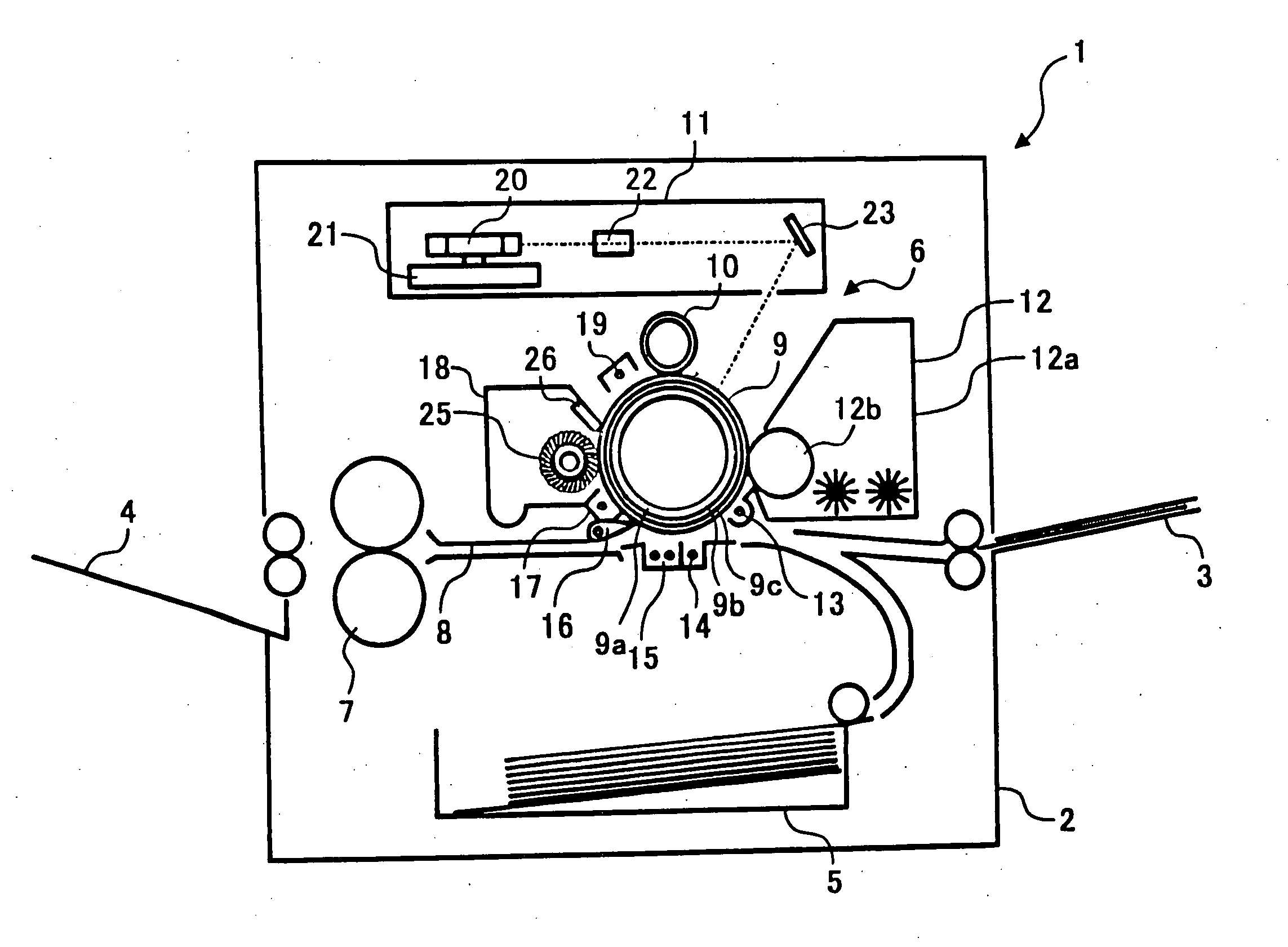
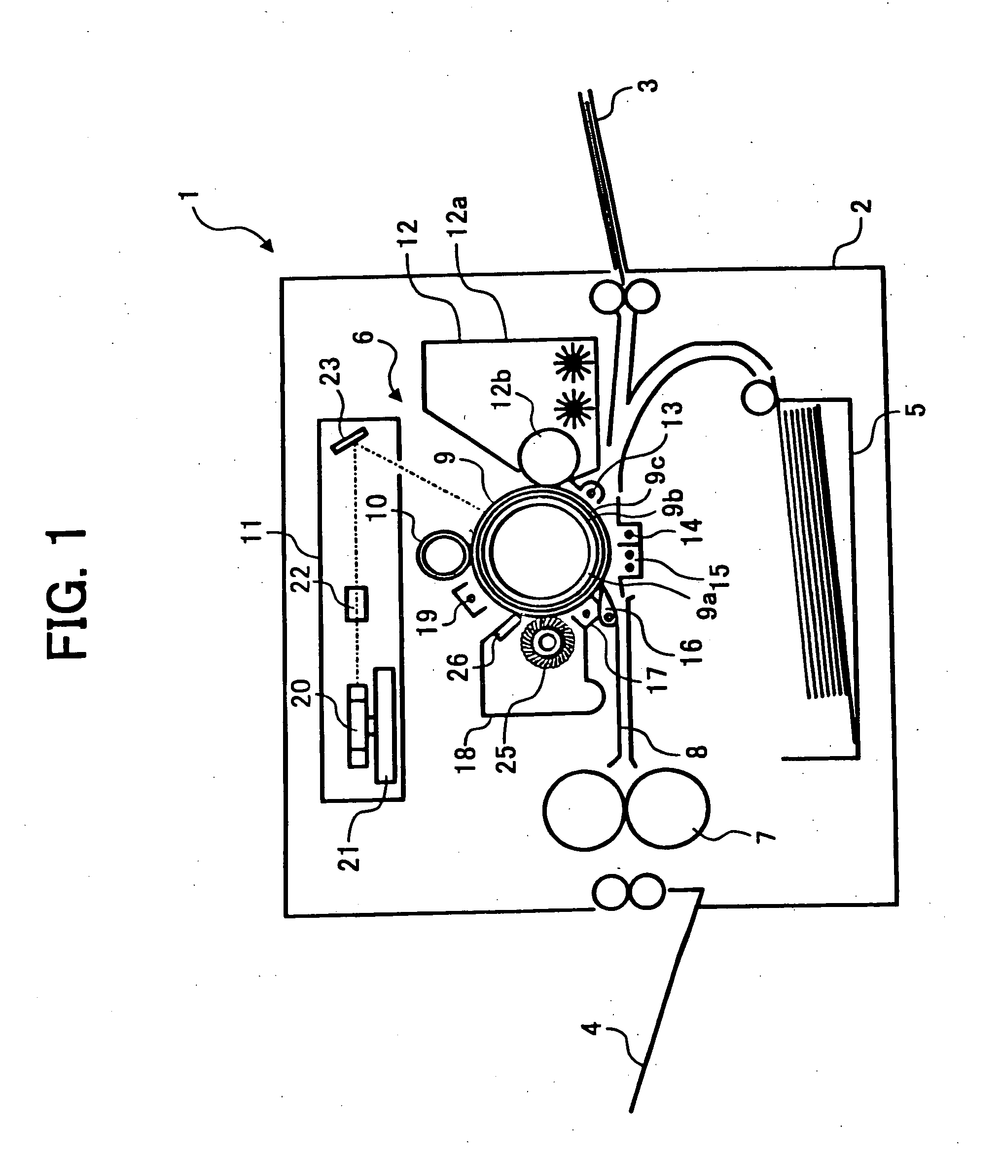
[0099] A printer in Example 1 includes a photoreceptor prepared by the following method.

[0100] After an intermediate layer coating liquid prepared by mixing and pulverizing with a ball mill the following components 10 was coated by a dip coating method on an electroconductive substrate which is an aluminium drum having a diameter of 100 the coated substrate was heated and dried to have an intermediate layer having a thickness of 3.5 μm.

Intermediate coating liquidAlkyd resin6(Bekkosol 1307-60-EL from Dainippon Ink &Chemicals, Inc.)Melamine resin4(Super Bekkamin G-821-60 from Dainippon Ink &Chemicals, Inc.)Titanium oxide40(CR-EL from Ishihara Sangyo Kaisha, Ltd.)Methyl ethyl ketone200

[0101] After a charge generation layer coating liquid prepared by mixing and dispersing with a ball mill the following components was coated on the intermediate layer, the coated substrate was heated and dried to have a charge generation layer having a thickness of 0.2 μm.

Charge generation layer coat...

example 2

[0108] The procedures of preparation for the printer in Example 1 were repeated to prepare a printer in Example 2 except for changing the formulation of the protection layer coating liquid as follows.

Protection layer coating liquidPolycarbonate50.6(Z-polyca from TEIJIN CHEMICALS LTD. havinga viscosity-average molecular weight of 50,000)Alumina2.7(Sumitomo Chemical Co., Ltd.)Disperser0.03Antioxidant0.31Charge transport material35.4having the formula (1)Cyclohexanone411.9Tetrahydrofuran1,467.2

example 3

[0109] The procedures of preparation for the printer in Example 1 were repeated to prepare a printer in Example 3 except for changing the formulation of the protection layer coating liquid as follows.

Protection layer coating liquidPolycarbonate18.4(Z-polyca from TEIJIN CHEMICALS LTD.having a viscosity-average molecular weightof 50,000)Alumina10(Sumitomo Chemical Co., Ltd.)Disperser0.1Antioxidant0.64Charge transport material12.9having the formula (1)Cyclohexanone166.7Tetrahydrofuran660.2

[0110] Subsequently, after 500,000 images and 1,000,000 images were produced by the printers prepared in Examples 1 to 3, the following items were evaluated.

[0111] Respective solid image densities; local defects such as black spots, white spots, black stripes and white stripes; and abnormal images such as background fouling were evaluated in a comprehensive manner and classified to three stages, i.e., “good”, “slightly poor” and “poor”.

[0112] Irradiated part potential of each photoreceptor when ha...


PUM

PropertyMeasurementUnit
average particle diameteraaaaaaaaaa

Abstract

An image forming apparatus including a photoreceptor having an electroconductive substrate, a photosensitive layer overlying the electroconductive substrate, and a protection layer including an inorganic filler in an amount of from 3 to 25% by weight based on total weight of the protection layer and a binder resin, and overlying the photosensitive layer. The apparatus further including a charger, an irradiator, an image developer, and a transferer transferring a toner image onto a transfer material. The apparatus also includes a cleaner cleaning the photoreceptor, including a rotatable core and a looped brush fiber provided on the surface of the rotatable core so as to contact the photoreceptor. A top of the looped brush fiber is positioned on an upstream side from a root of the looped brush fiber relative to a rotating direction of the rotatable core.

Description

BACKGROUND OF THE INVENTION [0001] 1. Field of the Invention [0002] The present invention relates to an image forming apparatus and a copier. [0003] 2. Discussion of the Background [0004] An electrophotographic process is typically one of image forming methods of charging a photoconductive photoreceptor in a dark place with, e.g., a corona discharge; irradiating the photoreceptor with imagewise light; forming an electrostatic latent image thereon by selectively scattering a charge on the irradiated part thereon; and developing the latent image with a toner including a colorant such as dyes and pigments and a binder such as polymers to form a visual toner image. [0005] Image forming apparatuses using the electrophotographic process include an electrophotographic printer, etc. Recently, the image forming apparatuses are required to have high durability in addition to producing high-quality images. [0006] A photoreceptor in the electrophotographic process repeatedly receiving mechanica...

Claims


Application Information

Patent Timeline
Patent Type & Authority Applications(United States)
IPC IPC(8): G03G21/00G03G5/04G03G5/047G03G5/05G03G5/147G03G21/10
CPCG03G5/0507G03G2221/001G03G21/0035G03G5/14704G03G21/0076
Inventor KURIMOTO, EIJIKITAJIMA, RYOHICHIKAWASAKI, YOSHIAKISUGINO, AKIHIROIKEGAMI, TAKAAKI
Owner RICOH KK
Why Eureka
Try Eureka