System and method for a distributed shared memory

a shared memory and distributed memory technology, applied in the field of distributed shared memory, can solve the problems of limiting the total system performance, limiting the total number of operations that can be done in any given unit of time, and limiting the total number of memory operations available to all processors

Inactive Publication Date: 2005-03-01
ORACLE INT CORP
View PDF5 Cites 145 Cited by
  • Summary
  • Abstract
  • Description
  • Claims
  • Application Information

AI Technical Summary

Problems solved by technology

This creates a bottleneck which limits total system performance in two ways.
First, the transport latency of getting a memory operation from a processor card to the shared memory card, and then getting the results back, limits the total number of operations that can be done in any given unit of time.
Second, since the shared memory operations for all of the processors are single threaded through the memory, the bandwidth of the memory limits the total number of memory operations available to all of the processors.
Further, the bandwidth of shared memory operations available to any given processor is limited to the memory bandwidth divided by the total number of processors.
However, such a distributed shared memory architecture creates a new set of problems that did not exist in the central shared memory architecture.

Method used


Image

  • System and method for a distributed shared memory
  • System and method for a distributed shared memory
  • System and method for a distributed shared memory

Examples


Embodiment Construction

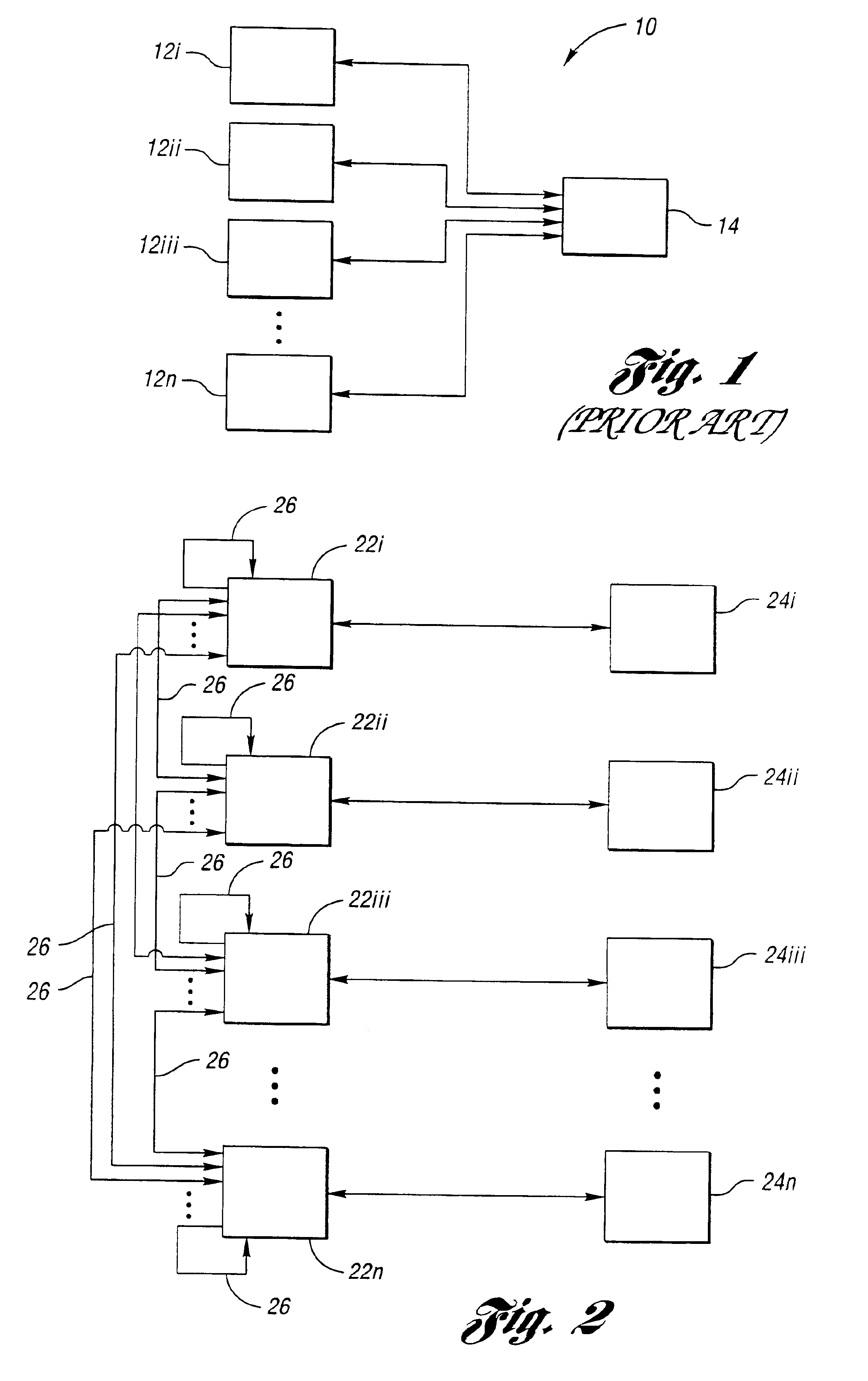
With reference to FIGS. 1-4, the preferred embodiment of the distributed shared system and method of the present invention will now be described in greater detail. Referring first to FIG. 1, a simplified block diagram of a centralized shared memory system architecture according to the prior art is shown, denoted generally by reference numeral 10. As seen therein, shared memory system (10) includes a plurality of processors (12i, 12ii, 12iii . . . 12n). The processors (12i, 12ii, 12iii . . . 12n) are each provided in communication with a single, centralized shared memory (14).

As previously noted, in such a prior art system architecture (10), centralized shared memory (14) is located on a circuit card separate from the circuit cards where the multiple processors (12i, 12ii, 12iii . . . 12n) are located. This creates a bottleneck which limits performance of the shared memory system (10) in two ways. First, as a result of the transport latency of getting a memory operation from a proces...


PUM


Abstract

A system and method for a distributed shared memory. The system includes multiple processors, each processor transmitting write commands issued therefrom concerning a shared memory to each of the processors, such that each processor receives each shared memory write command transmitted. The system also includes multiple local memories, each local memory associated with one of the processors and having a copy of the shared memory, wherein each processor completes each received shared memory write command at its associated local memory such that the copies of the shared memory remain consistent at all times. The method includes transmitting write commands concerning the shared memory to each of the processors, such that each processor receives each shared memory write command transmitted, and completing each received shared memory write command at the associated local memory such that the copies of the shared memory remain consistent at all times.

Description

TECHNICAL FIELDThe present invention relates generally to a system and method for a distributed shared memory and, more particularly, to a distributed shared memory system and method including a plurality of local memories, each local memory having a copy of the shared memory, wherein the copies of the shared memory remain consistent at all times.BACKGROUND ARTIn present Shared Virtual Array (SVA) systems, the centralized shared memory is located on a circuit card separate from the circuit cards where the multiple processors are located. This creates a bottleneck which limits total system performance in two ways. First, the transport latency of getting a memory operation from a processor card to the shared memory card, and then getting the results back, limits the total number of operations that can be done in any given unit of time. Second, since the shared memory operations for all of the processors are single threaded through the memory, the bandwidth of the memory limits the tot...

Claims


Application Information

Patent Timeline
Patent Type & Authority Patents(United States)
IPC IPC(8): G06F15/16G06F15/173
CPCG06F15/17381
Inventor BUHLMAN, CRAIG A.CASORSO, ANTHONY J.
Owner ORACLE INT CORP
Why Eureka
Try Eureka