
Virtualization bridge device

Active Publication Date: 2011-07-12
AVAGO TECH INT SALES PTE LTD
View PDF31 Cites 133 Cited by
  • Summary
  • Abstract
  • Description
  • Claims
  • Application Information

AI Technical Summary

Problems solved by technology

This introduces the problem of sharing an I / O device among multiple operating systems.
One problem is the endpoint extensions for SR-IOV and MR-IOV are different, so with current designs endpoint manufacturers have to generate two different products if they desire to satisfy both markets.

Method used


Image

  • Virtualization bridge device
  • Virtualization bridge device
  • Virtualization bridge device

Examples


Embodiment Construction

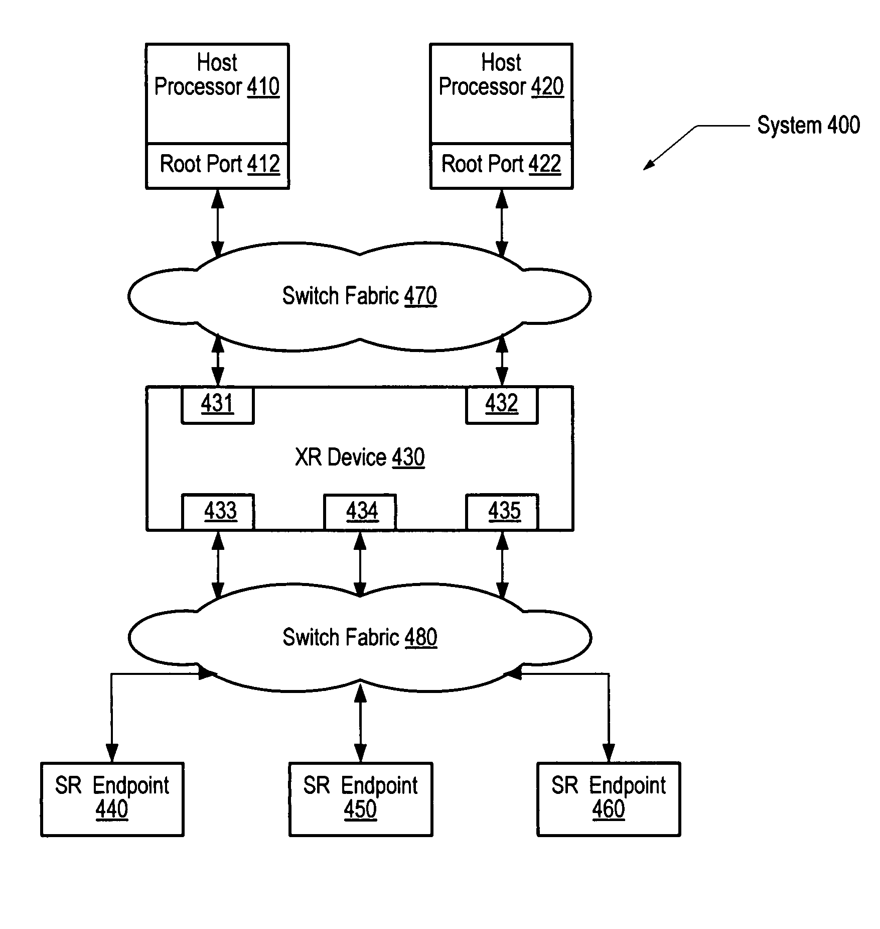
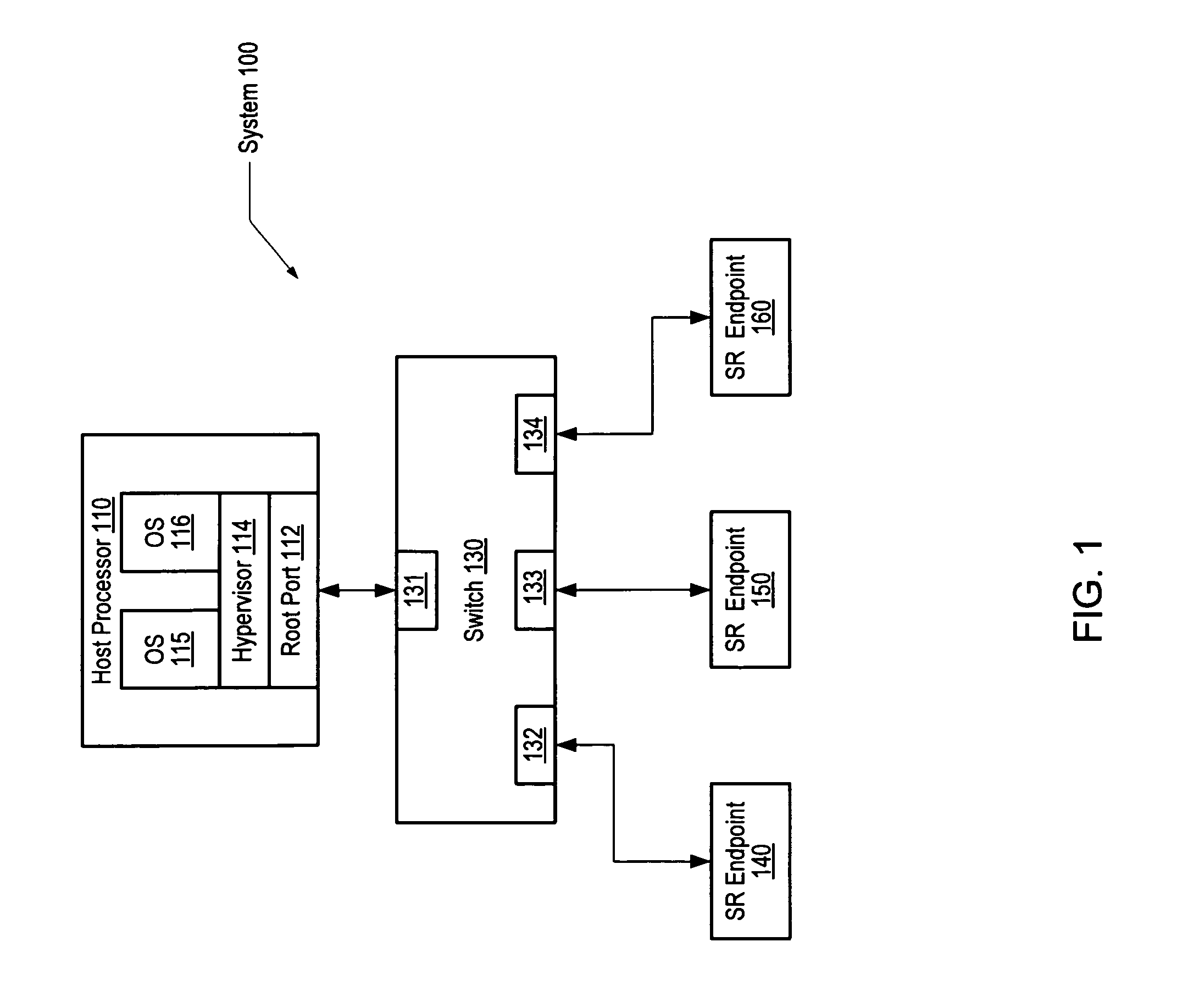
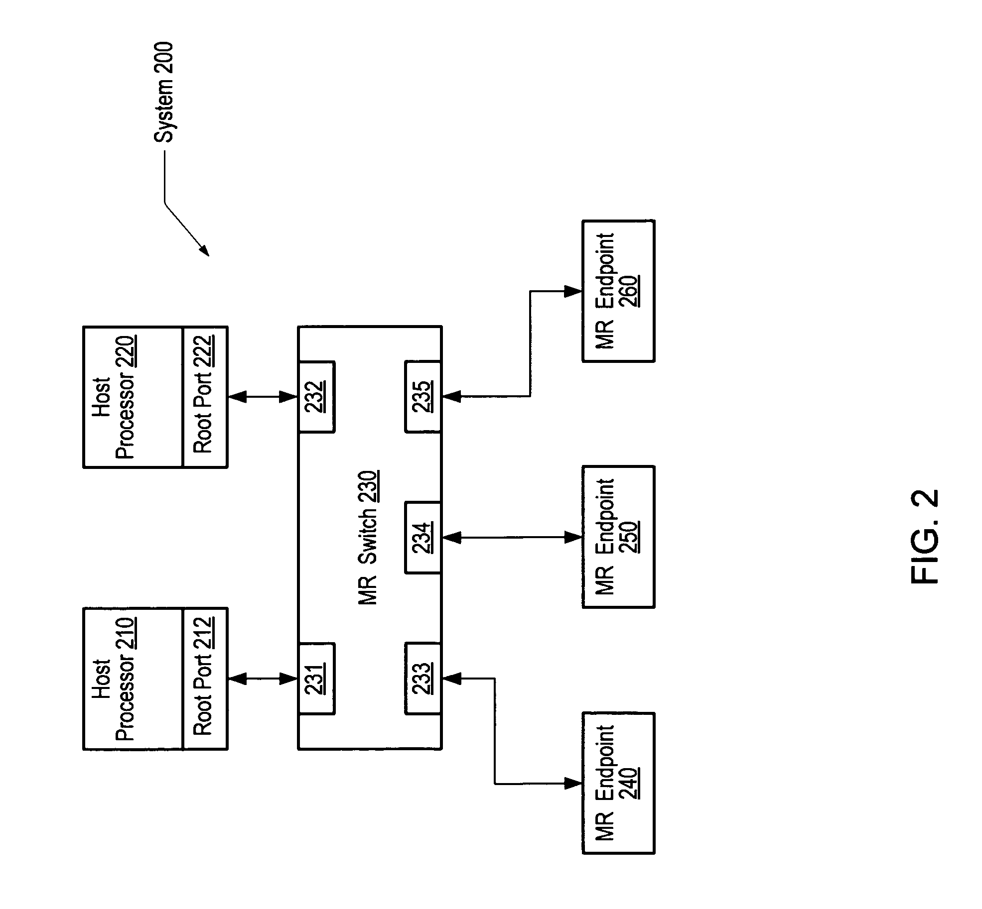
[0041]The following description is generally organized as follows. The first section includes FIG. 4 and provides an overview of one embodiment of an MR system in which SR endpoints may be used. FIG. 5 provides a software model of a system in which an SR endpoint is shared in an MR system. FIG. 6 illustrates a virtual model of an MR switch configured to share an SR endpoint. FIG. 7 illustrates the process by which an SR endpoint is shared in an MR system. FIGS. 8-14 illustrate various aspects of a device that may be used to implement the concepts shown in FIG. 7. Finally, FIGS. 15, 16, 17, and 18 illustrate various virtual hierarchies that may be implemented using the device.

System Overview

[0042]FIG. 4 illustrates a generalized block diagram of one embodiment of an MR-IOV computer system 400 in which SR endpoints may be used. For convenience, system 400 and similar systems may be referred to hereinafter as XR systems. In the illustrated embodiment, single host processors 410 and 420...


PUM


Abstract

A computer system includes a shared I / O device including functions providing access to device local memory space, and a plurality of roots coupled to the shared I / O device via a switch fabric. A first root assigns a first address in a first root memory space to a first function. A second root assigns a second address in a second root memory space to a second function. The switch fabric maps the first root memory space to a first portion of device local memory space and the second root memory space to a second portion of device local memory space. Subsequently, the switch receives a data transaction request from the first root targeted to the first address, translates the first address to a corresponding location in the first portion of the device local memory space based on the mapping, and routes the data transaction request to the I / O device.

Description

CROSS REFERENCE TO RELATED APPLICATIONS[0001]This application claims the benefit of priority to U.S. Provisional Patent Application No. 60 / 888,984, entitled “Virtualization Bridge Device,” filed Feb. 9, 2007, the entirety of which is incorporated herein by reference.BACKGROUND OF THE INVENTION[0002]1. Field of the Invention[0003]This invention relates generally to the field of computer system architecture and more particularly, to an architecture that allows mapping between computing nodes and shared or non-shared I / O devices.[0004]2. Description of the Related Art[0005]Computing systems often contain multiple compute nodes. For example, computing systems may include multiple CPUs, one or more multi-core CPUs, CPUs that operate in multiple operating system domains, and / or multiple single-board computers configured as blades and mounted in a common chassis or drawer. In addition, computer nodes may be interfaced to multiple I / O devices. I / O devices may be any devices that allow data ...

Claims


Application Information

Patent Timeline
IPC IPC(8): G06F3/00
CPCG06F13/404
Inventor PETTEY, CHRISTOPHER J.GLASER, STEPHENKHAN, ASIFNALLEY, JONROUSSET, STEPHENSAEGER, TOMUTLEY, ROBERT HASKELL
Owner AVAGO TECH INT SALES PTE LTD
Learn More