
Sports shoe sole

Inactive Publication Date: 2005-03-08
CALZATURIFICIO S C A R P A
View PDF11 Cites 14 Cited by
  • Summary
  • Abstract
  • Description
  • Claims
  • Application Information

AI Technical Summary

Benefits of technology

It is an object of the present invention to provide a sports shoe sole designed to solve the aforementioned problems, and which, in particular, provides for good grip combined with safe footing and comfort.

Problems solved by technology

Currently marketed soles, however, fail to provide an optimum solution to the two conflicting requirements of ensuring safe footing, which would call for a substantially rigid sole, and a fairly good degree of comfort.

Method used


Image

  • Sports shoe sole
  • Sports shoe sole
  • Sports shoe sole

Examples


Embodiment Construction

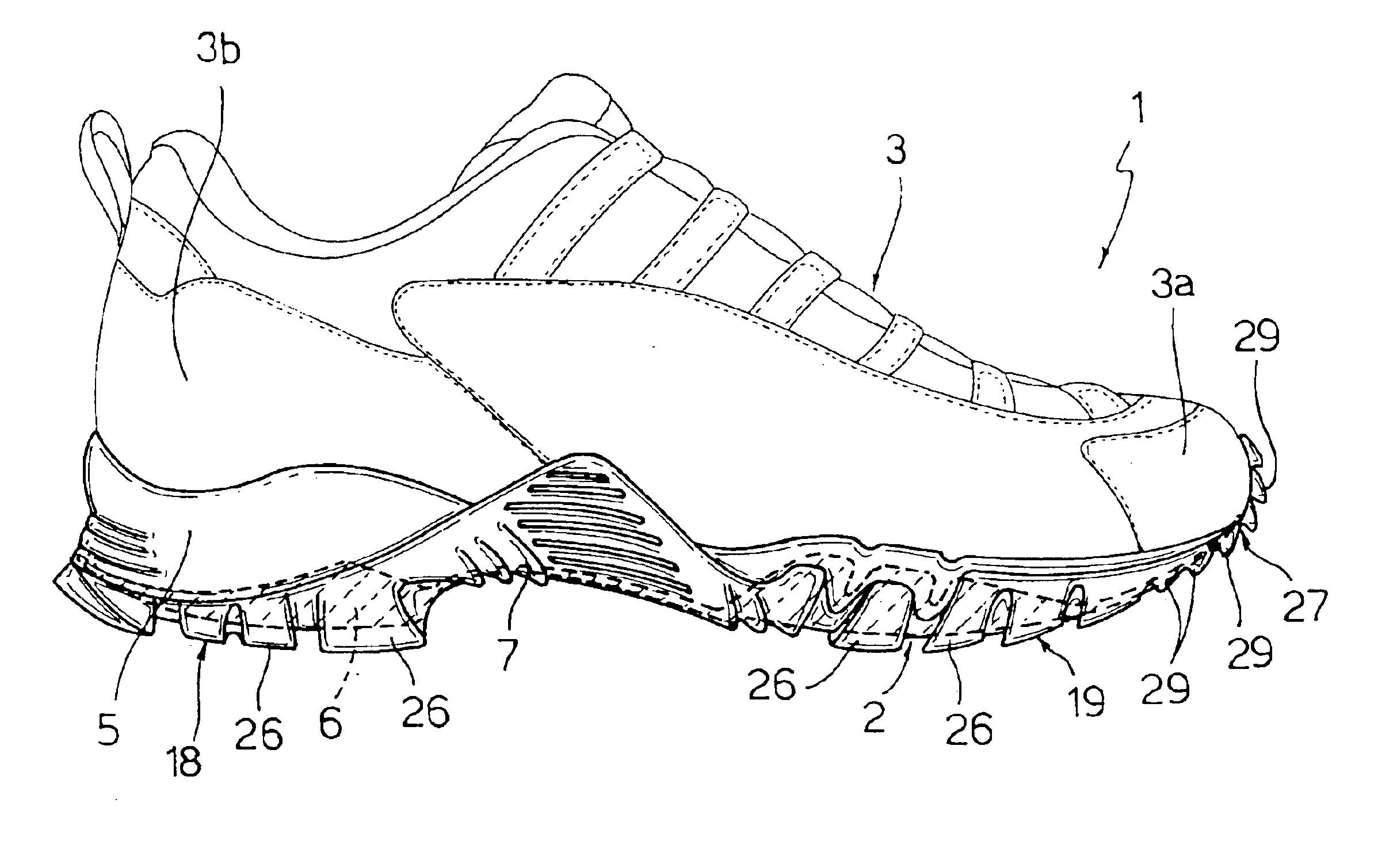
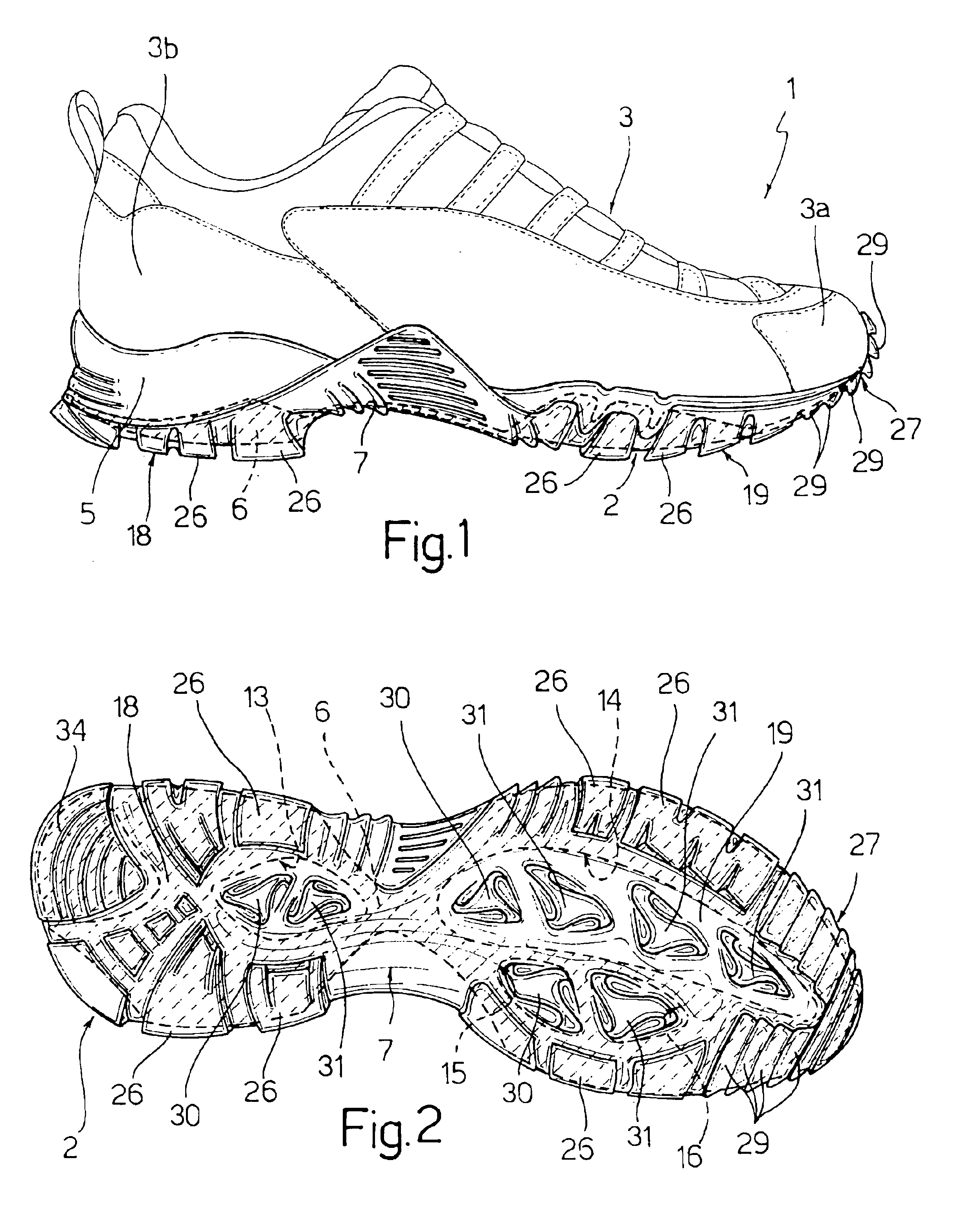
Number 1 in FIG. 1 indicates as a whole a light-hiking shoe comprising a sole 2 and a vamp 3.

Vamp 3 comprises a toe portion 3a, and a heel portion 3b corresponding with the heel of the wearer.

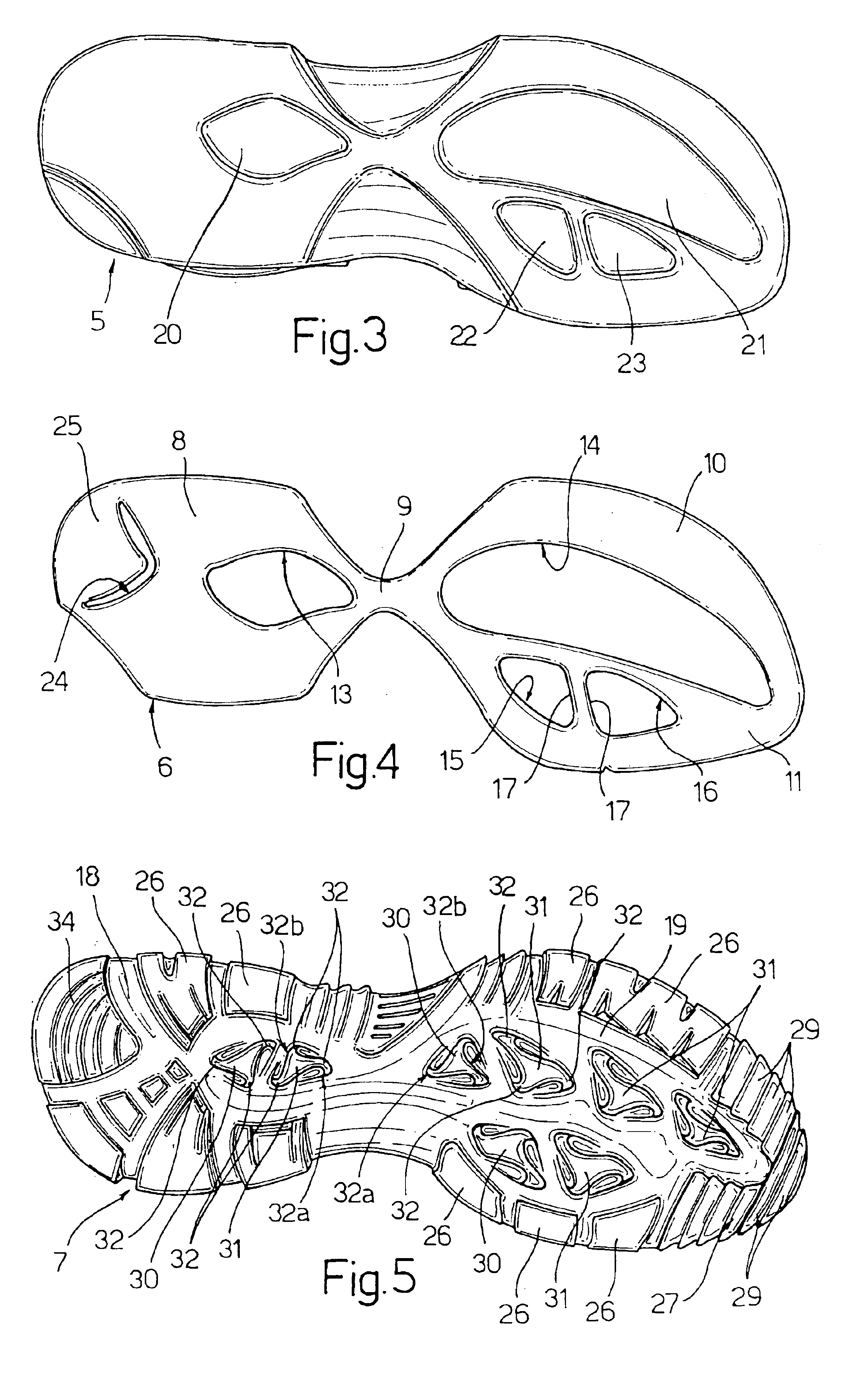
More specifically, and as shown in FIGS. 3, 4 and 5, sole 2 comprises a top or cushioning layer 5, an intermediate layer or frame 6, and a bottom layer or tread 7, placed and fixed, e.g. glued, one on top of another.

Cushioning layer 5 is made of relatively soft, flexible polymer foam material, preferably polyurethane foam, for effective shock absorption and comfortable support.

Frame 6 is made of thermoplastic material to provide the necessary mechanical strength—in particular, torsional rigidity—of sole 2.

Frame 6 (FIG. 4) is substantially figure-8-shaped, is slightly smaller in area than cushioning layer 5, and comprises a rear portion 8 at the heel, a narrow intermediate portion 9, and a front portion 10 at the forefoot.

Front portion 10 terminates at the front in a tapered toe portion 11 exten...


PUM


Abstract

A sports shoe sole has a cushioning layer, a frame and a tread. The frame has through openings housing corresponding projections of the cushioning layer. The tread has a number of rocking locks located to correspond with the openings, and each having differently deformable portions located one in front of the other to provide uphill and downhill grip.

Description

The present invention relates to a sports shoe sole, in particular for a light-hiking or trekking shoe.BACKGROUND OF THE INVENTIONAs is known, soles differ according to whether they are designed for comfort, safe footing or grip.Light-hiking shoe soles are normally defined by two or more layers comprising at least one bottom layer or tread of elastomeric material, and a top layer of flexible cushioning material for supporting the foot.When walking, the sole should ensure maximum grip on any surface or gradient, and in particular sufficient friction to prevent backward sliding uphill and ensure optimum braking downhill.For this purpose, soles are now marketed featuring a tread with a number of deformable, projecting blocks, which are normally substantially quadrangular and constitute a compromise solution designed to achieve acceptable grip performance when accelerating and decelerating.Currently marketed soles, however, fail to provide an optimum solution to the two conflicting requ...

Claims


Application Information

Patent Timeline
IPC IPC(8): A43C15/00A43C15/16A43B13/22A43B13/02A43B13/14A43B13/12A43B5/00
CPCA43B5/002A43B13/026A43C15/162A43B13/223A43B13/12
Inventor PARISOTTO, DAVIDE
Owner CALZATURIFICIO S C A R P A
Learn More