Railroad car energy absorption apparatus

a technology for energy absorption and rail cars, which is applied in mechanical equipment, machines/engines, transportation and packaging, etc., can solve the problems of reducing the effective use of rail car parts. , to achieve the effect of prolonging the effective usefulness of the side bearing assembly, promoting heat dissipation, and limiting adverse effects

Inactive Publication Date: 2005-03-08
MINER ENTERPRISES INC
View PDF1 Cites 19 Cited by
  • Summary
  • Abstract
  • Description
  • Claims
  • Application Information

AI Technical Summary

Benefits of technology

In view of the above, there is provided a railroad car energy absorption apparatus which is specifically designed to limit the adverse affects local heat has on such apparatus. In accordance with one aspect of the invention, a railroad car side bearing assembly is adapted to be disposed intermediate an elongated bolster and a car body of a railway vehicle. The side bearing includes a housing and a cap or top plate which is movable toward and away from the housing. Both the housing and cap include wall structure which, when

Problems solved by technology

Suffice it to say, excessive hunting can result in premature wear of the wheeled truck components including the wheels.
Hunting can also cause damage to lading being transported in the railroad car body.
The spring loaded steel elements, utilizing a steel on steel friction interface, proved ineffective in some applications because of seizing and galling problems.
Regardless of the application, the buildup of heat in proximity to the thermoplastic spring is a serious concern.
Unless such heat buildup can be controlled, however, the thermoplastic spring will tend to soften and deform, thus, adversely affecting the operable performance of the railroad component with which it finds utility.
Such resulting friction also typically causes an excessive amount of heat at the interface between the top plate and the underside of the car body.
Such heat buil

Method used


Image

  • Railroad car energy absorption apparatus
  • Railroad car energy absorption apparatus
  • Railroad car energy absorption apparatus

Examples


Embodiment Construction

The present invention is susceptible of embodiment in multiple forms and there is shown and will hereinafter be described preferred embodiments of the invention, with the understanding the present disclosure is to be considered as setting forth exemplifications of the invention which are not intended to limit the invention to the specific embodiments illustrated and described.

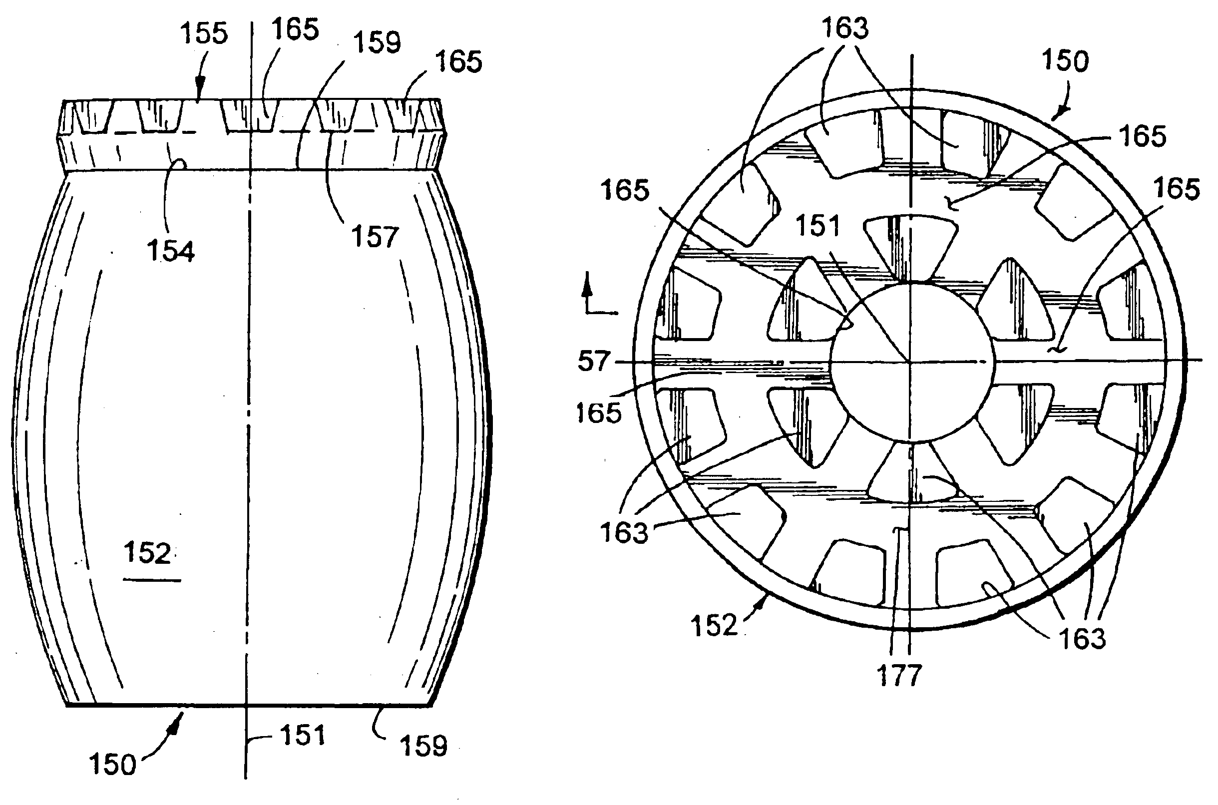
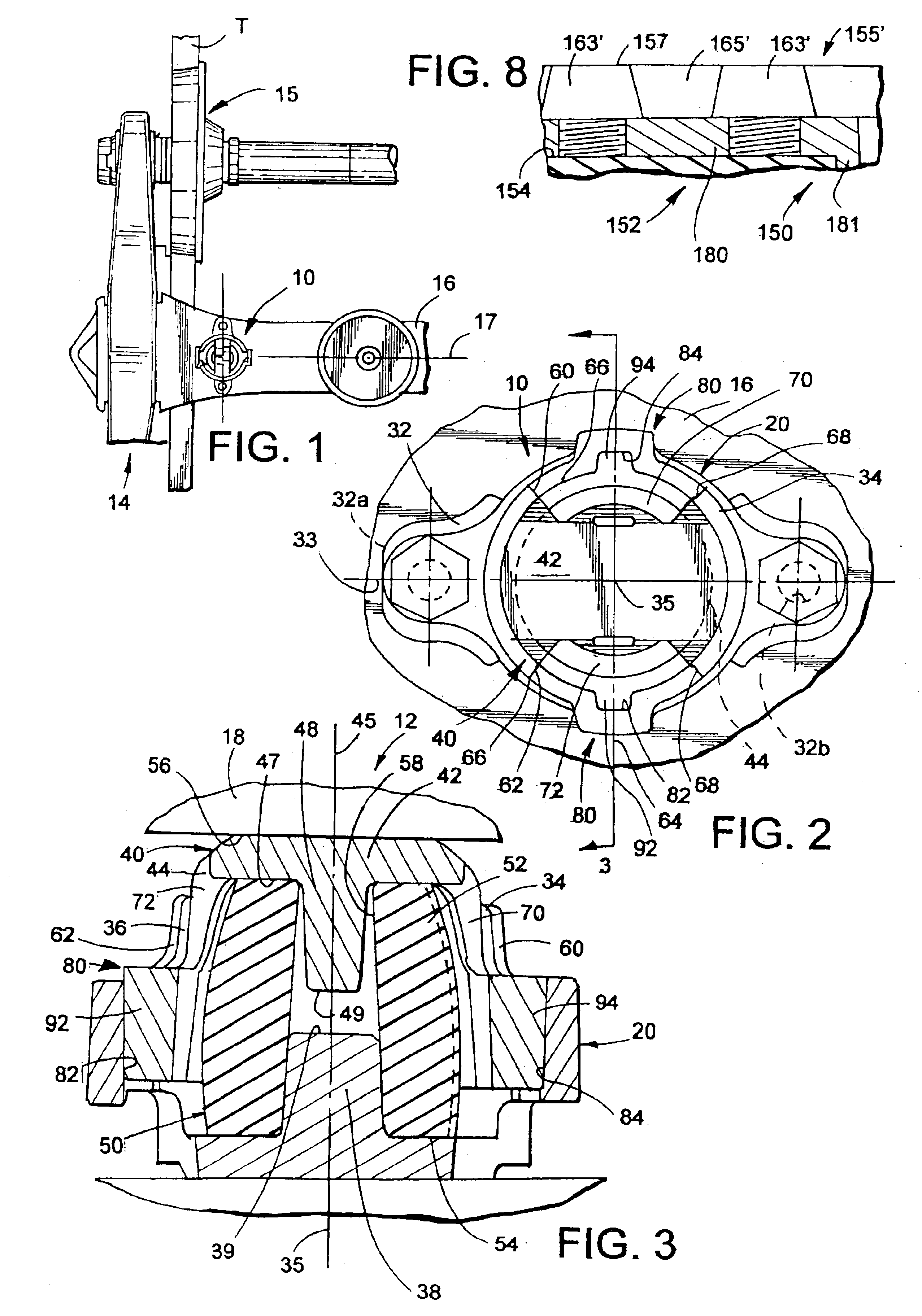
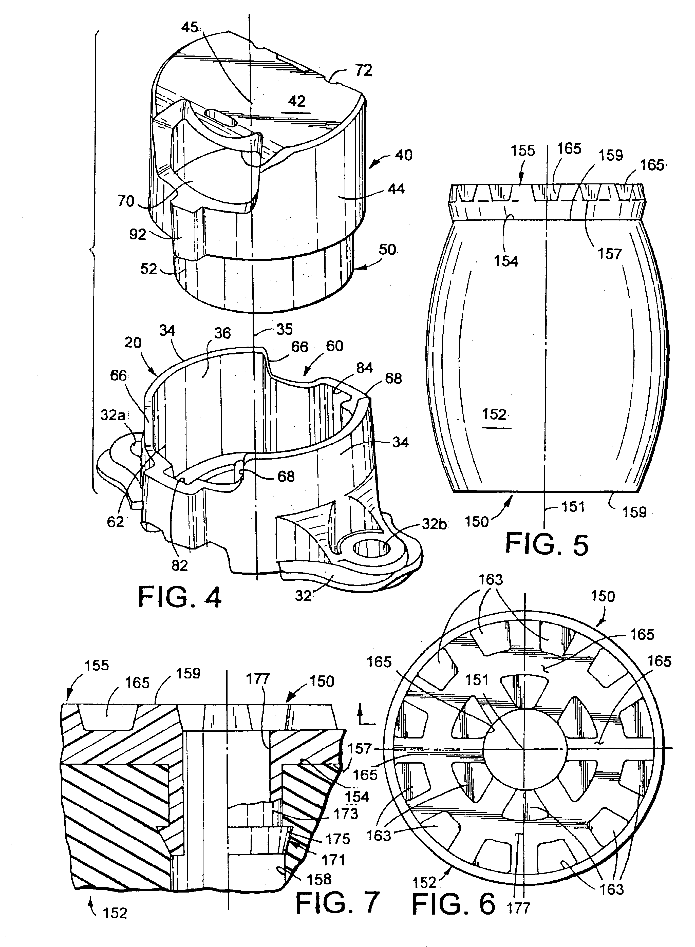
Referring now to the drawings, wherein like reference numerals refer to like parts through out the several views, a railroad car energy absorption apparatus is shown in FIG. 1 and is generally identified by reference numeral 10. The railroad car energy absorption apparatus 10 can take a myriad of different shapes without detracting or departing from the true spirit and scope of the present invention. In one embodiment, the energy absorption apparatus 10 is shown as a railroad car side bearing which is mounted on a railroad car 12 (FIG. 3). More specifically, the side bearing 10 is mounted on and in operable com...


PUM


Abstract

A railroad car energy absorption apparatus is disclosed. The railroad car energy absorption apparatus includes a spring assembly having an elastomer spring element arranged in operable combination with structure for inhibiting localized heat deterioration of the elastomer spring element.

Description

FIELD OF THE INVENTIONThe present invention generally relates to a railroad car energy absorption apparatus and, more particularly, to a railroad car energy absorption apparatus including a spring assembly having an elastomer spring element arranged in operable combination with structure for inhibiting localized heat deterioration of the elastomer spring element.BACKGROUND OF THE INVENTIONAn energy absorption apparatus is known to be utilized on a railroad car in various applications and between two masses. For example, an energy absorption apparatus is typically arranged in operable combination with a railroad car draft gear for absorbing forces between adjacent ends of railroad cars. A railroad car energy absorption apparatus is also commonly configured as a side bearing. A railroad car side bearing is typically disposed to opposite sides of a car body between a centerpiece or bolster of a wheeled truck and an underside of the railroad car body. During movement of the railcar, eac...

Claims


Application Information

Patent Timeline
IPC IPC(8): B61F5/02B61F5/14F01M1/00
CPCB61F5/142
Inventor O'DONNELL, WILLIAM P.VANMALDEGIAM, MICHAEL D.JENSEN, ERIK D.WILT, DONALD E.DILLON, MICHAEL S.
Owner MINER ENTERPRISES INC
Why Eureka
Try Eureka