Method of forming a color filter

a color filter and color technology, applied in the field of printing, can solve the problems of not being able to easily form patterned layers of thermally unstable color filter materials, not being able to solve the problems of environmental pollution, not being able to solve the problems of thermal pollution,

Inactive Publication Date: 2005-03-08
EASTMAN KODAK CO
View PDF13 Cites 38 Cited by
  • Summary
  • Abstract
  • Description
  • Claims
  • Application Information

AI Technical Summary

Problems solved by technology

As is known in the art, these processes are not adapted to generate patterned layers of thermally unstable color filter materials.
This method is disadvantaged because the ink compositions, which include the color filter material, have high solvent concentrations which enables the ejection of the ink composition using conventional inkjet printers.
Additionally, the color filter materials used will not always dissolve or solubilize in commonly available solvents.
This can necessitate the use of exotic solvents that are environmentally harmful and/or expensive.
There is a problem with this technology in that the marking material and propellant stream are two different entities and the propellan

Method used


Image

  • Method of forming a color filter
  • Method of forming a color filter
  • Method of forming a color filter

Examples


first embodiment

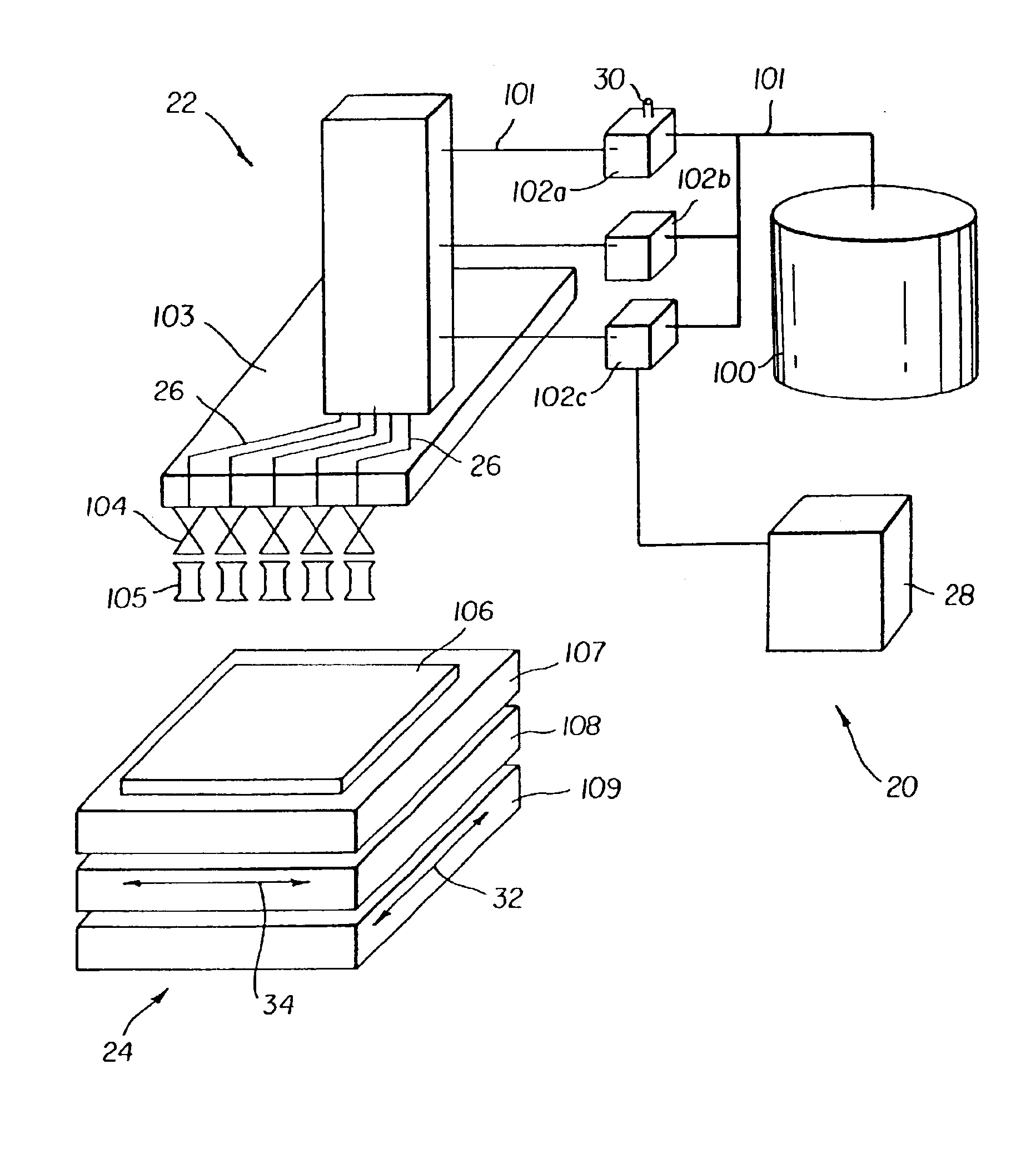
Referring to FIG. 1, a first embodiment is shown. The printhead 103 which includes at least one discharge device 105 and at least one actuating mechanism 104 remains stationary during operation. However, the printhead 103 can maintain a limited movement capability as is required to dither the image (typically from one to two pixels in length). A receiver 106 positioned on a receiver retaining device 24 moves in a first direction 32 and a second direction 34. Typically, the second direction 34 is substantially perpendicular to the first direction 32. The two directional motion of receiver 106 can be achieved by using a receiver retaining device 24 having a first motorized translation stage 108 positioned over a second motorized translation stage 109.

In this embodiment, the printhead 103 can be connected to the formulation reservoir(s) 102a, 102b, 102c using essentially rigid, inflexible tubing 101. As the color filter material delivery system is typically under high pressure from the...

second embodiment

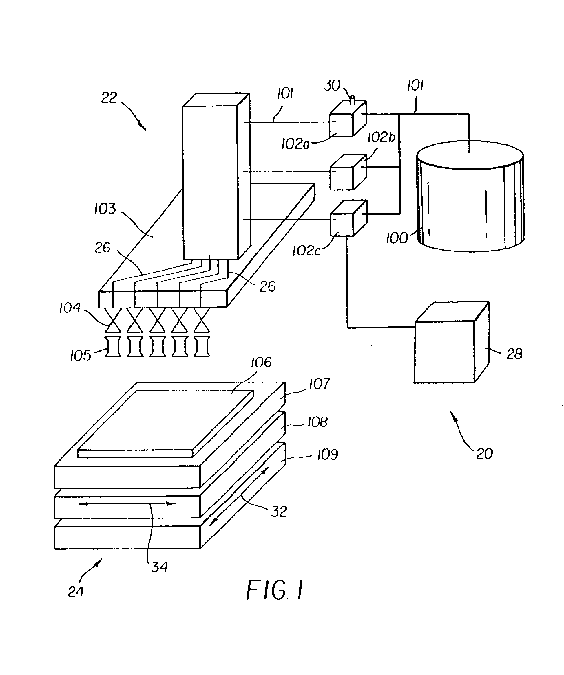
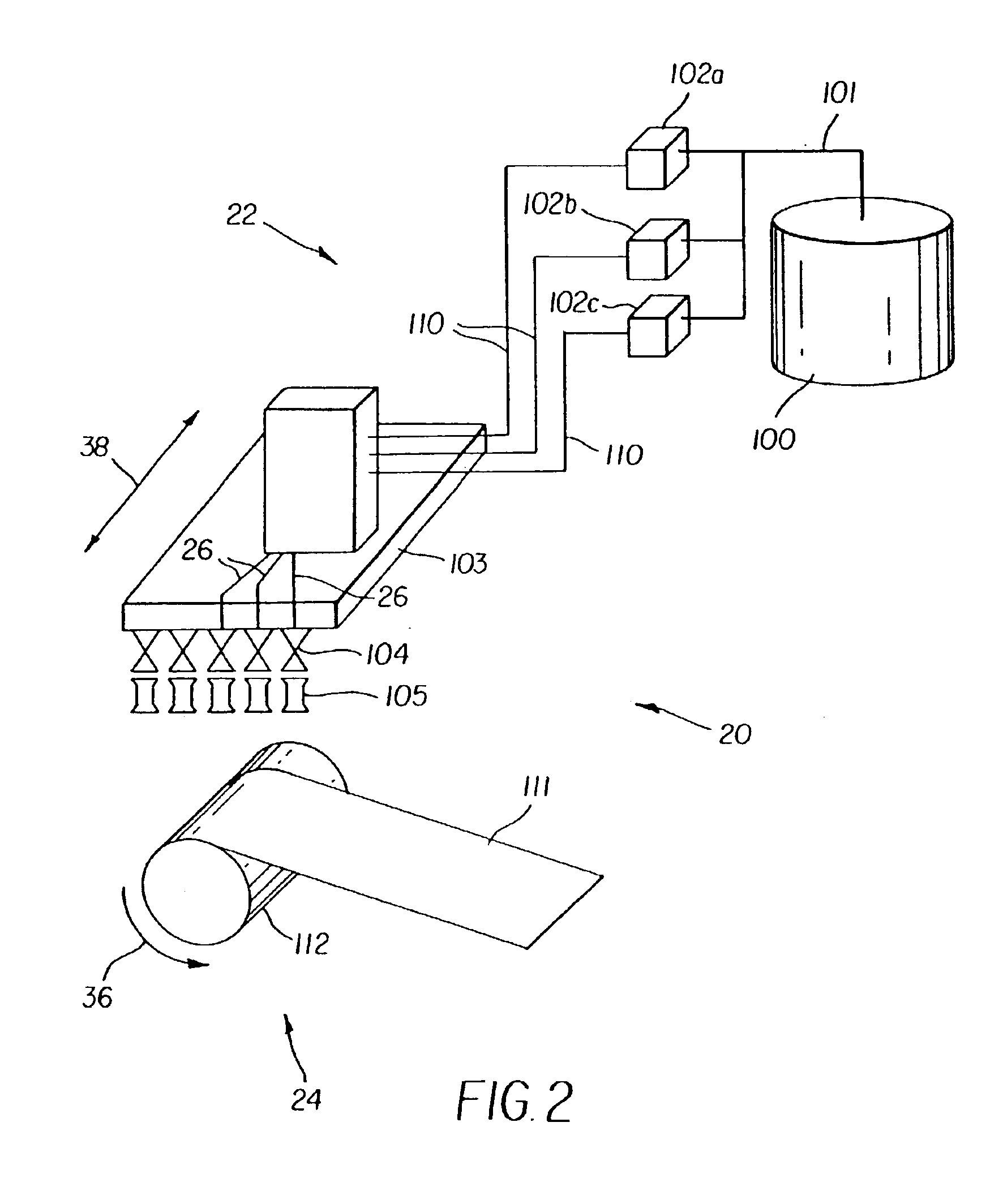
Referring to FIG. 2, a second embodiment is shown. In this embodiment the receiver retaining device 24 is a roller 112 that provides one direction of motion 36 for a receiver 11 while the printhead 103 translates in a second direction 38. Rigid tubing 101 connects the compressed fluid source 100 to the formulation reservoir(s) 102a, 102b, 102c. However, the printhead 103 is connected to the formulation reservoir(s) 102a, 102b, 102c by a flexible high pressure tube(s) 110. A suitable flexible hose can be, for example, a Titeflex extra high pressure hose P / N R157-3 (0.110 inside diameter, 4000 psi rated with a 2 in bend radius) commercially available from Kord Industrial, Wixom, Mich. The compressed fluid source 100 is remotely positioned relative to the printhead 103.

In a multiple material printing operation, each material is applied in a controlled manner through the actuating mechanisms 104 and discharge devices 105 of printhead 103 as the printhead 103 translates in second directi...

third embodiment

Referring to FIG. 3, a third embodiment is shown. In this embodiment, the color filter material delivery system 22 includes a compressed fluid source 115 positioned on the printhead 103. The compressed fluid source 115 is in fluid communication with the formulation reservoir(s) 102a, 102b, 102c through delivery path(s) 40 located on or in the printhead 103. The formulation reservoir(s) 102a, 102b, 102c are connected in fluid communication with the discharge device(s) 105 through delivery path(s) 26 positioned on or in the printhead 103.

The compressed fluid source 100 is connected to a docking station 113 which mates with a recharging port 114 of the compressed fluid source 115 located on the printhead 103. This allows the compressed fluid contained in the compressed fluid source 115 located on the printhead 103 to be replenished as is required during a printing operation. Recharging can occur in a variety of situations, for example, recharging can occur when a predetermined remainin...


PUM


Abstract

A method of forming a color filter and a color filter are provided. The method includes providing a mixture of a color filter material and a compressed fluid; providing a substrate; providing a printhead adapted to deliver the mixture of the color filter material and the compressed fluid toward the substrate; positioning the printhead in a predetermined location relative to the substrate; and ejecting the mixture of the color filter material and the compressed fluid through the printhead toward the substrate, wherein the color filter material becomes free of the compressed fluid prior to the color filter material contacting the substrate at the predetermined location.

Description

FIELD OF THE INVENTIONThis invention relates generally to printing and more particularly, to printing using solvent free materials.BACKGROUND OF THE INVENTIONColor filters and the methods used to manufacture color filters are known. Color filter producing methods include techniques that deposit color filter material onto a prepatterned substrate. These techniques include, for example, vapor deposition, spin-coating, and thermal deposition (see, for example, U.S. Pat. No. 5,874,188, issued to Roberts et al., on Feb. 23, 1999).Other methods of manufacturing color filters involve evaporating the color filter material, using heat or ion bombardment, and then depositing the evaporated color filter material onto a substrate using a condensation process or a chemical reaction. In these manufacturing processes, the color filter material must to be thermally stable or have a thermally stable precursor that generates the color filter material on the substrate (when a chemical reaction process...

Claims


Application Information

Patent Timeline
IPC IPC(8): B41J2/04B41J2/21B05B15/04B41J2/01B41J2/175B41J2/015
CPCB41J2/211B41J2/04
Inventor SADASIVAN, SRIDHARJAGANNATHAN, RAMESHJAGANNATHAN, SESHADRIMEHTA, RAJESH V.NELSON, DAVID J.IRVIN, JR., GLEN C.
Owner EASTMAN KODAK CO
Why Eureka
Try Eureka