
Expandable polymer dental implant and method of use

a polymer and dental implant technology, applied in dental implants, dental surgery, medical science, etc., can solve the problem of difficult removal of traditional metallic implants

Inactive Publication Date: 2005-03-08
DYNAMIC IMPLANTS
View PDF41 Cites 24 Cited by
  • Summary
  • Abstract
  • Description
  • Claims
  • Application Information

AI Technical Summary

Benefits of technology

"The patent text describes improved dental implant systems and methods that use a polymer sheath as an artificial periodontal membrane. The rigid implant is inserted within the polymer sheath and causes expansion of the sheath when fitted within the sheath. An abutment is provided to couple the rigid implant and permits attachment of a dental prosthesis. The systems and methods also make possible the ability to post-operatively remove the implant in the event that modifications need to be made. The technical effects of the invention include improved dental implant procedures that provide better stability and flexibility, as well as easier removal and replacement of the implant."

Problems solved by technology

Removal of the traditional metallic implant is very difficult due to osteo in-growth and once removed the replacement requires another waiting period for proper in-growth to take place.

Method used


Image

  • Expandable polymer dental implant and method of use
  • Expandable polymer dental implant and method of use
  • Expandable polymer dental implant and method of use

Examples


Embodiment Construction

Although the disclosure hereof is detailed and exact to enable those skilled in the art to practice the invention, the physical embodiments herein disclosed merely exemplify the invention that may be embodied in other specific structures.

Dental Implant With Expandable Polymer Sheath

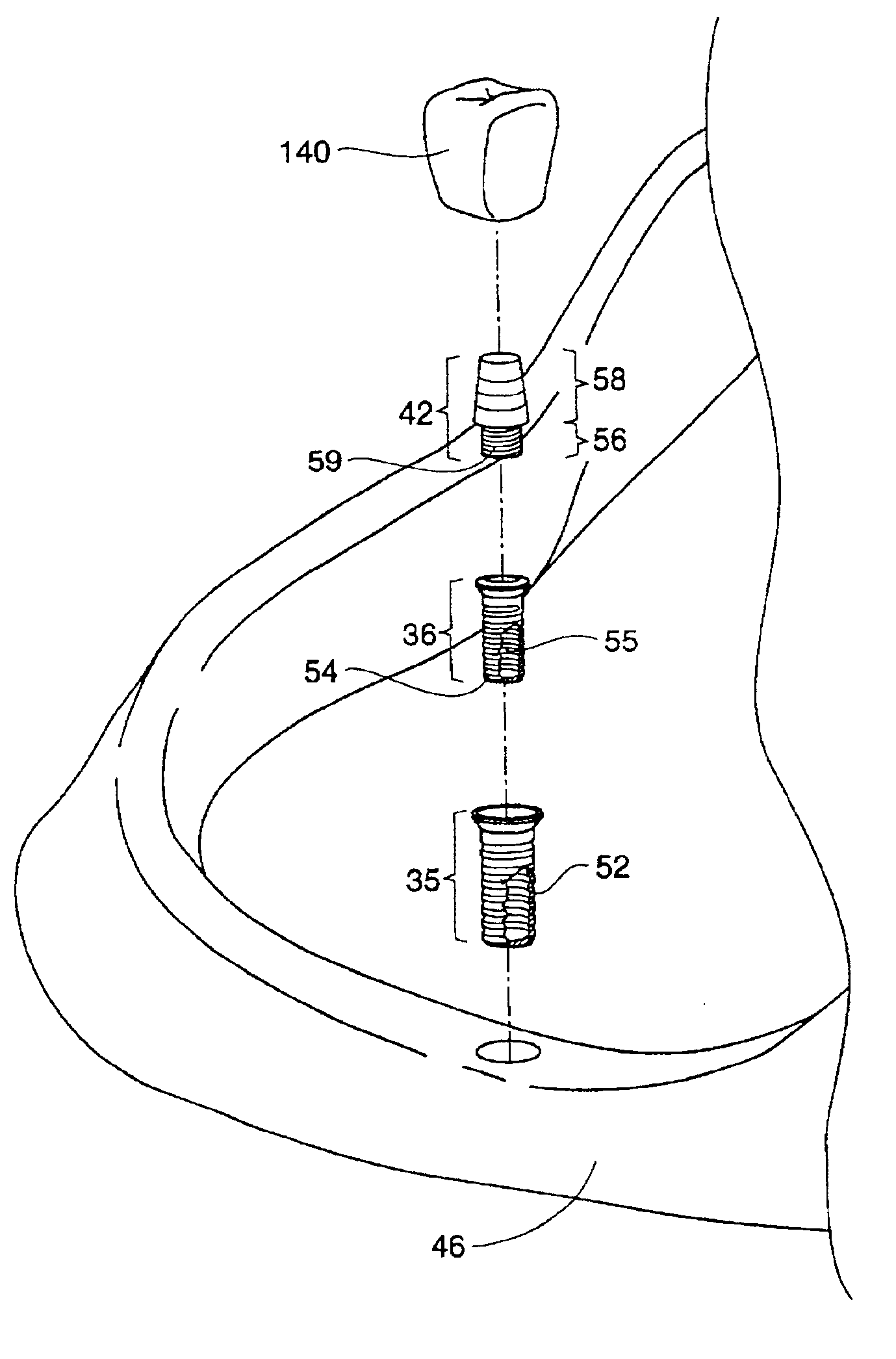
FIG. 6 shows a dental implant system 34 suitable for an endosteal implant into a jawbone 46. The system comprises an expandable polymer sheath 35, an implant 36, and an abutment permitting the attachment of a dental prosthesis 44. Details of each of these system components will now be described in detail.

A. The Expandable Polymer Sheath

As seen in FIG. 6, the system 34 provides an expandable polymer sheath 35. The sheath 35 serves to receive the implant 36 and provides an artificial periodontal membrane 24, i.e., the sheath 35 mimics the periodontal membrane 24 by performing a like cushioning function.

The sheath 35 is a hollow cylindrical body having a closed bottom end portion and an open top end portion....


PUM


Abstract

Systems and methods for a dental implant system suitable for an endosteal implant into a jawbone are provided. The systems and methods make use of an expandable polymer sheath insertable into a jawbone, an implant insertable into the sheath and causing expansion of the sheath upon insertion, and an abutment adapted to be coupled to the implant and permitting the attachment of a dental prosthesis.

Description

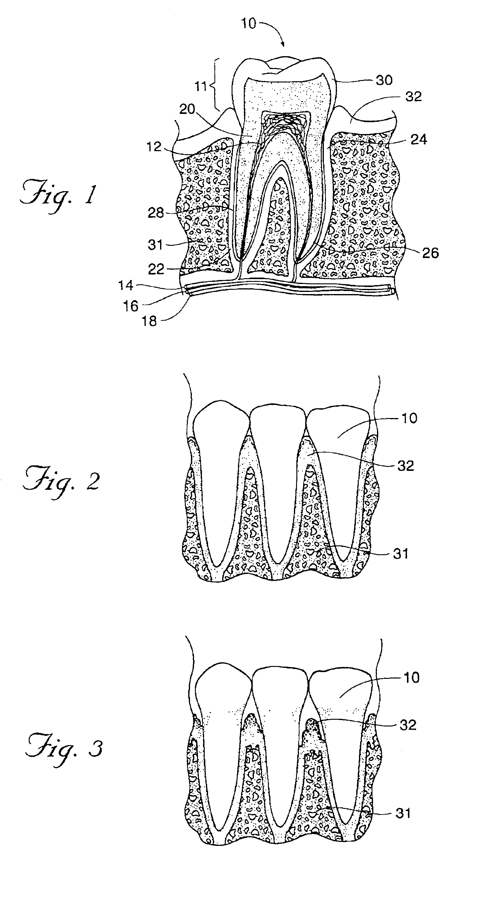
FIELD OF THE INVENTIONThis invention generally relates to dental implants and methods for installing such implants. rane.BACKGROUND OF THE INVENTIONHuman teeth vary in shape in accordance with their position and function, but share a common structure. As seen in FIG. 1, a tooth 10 consists of a central pulp 12 that communicates with arteries 14, veins 16, and nerves 18. This pulp 12 is surrounded by a calcareous substance known as dentin 20.As also seen in FIG. 1, the teeth project from sockets 22, or alveoli dentalis, in the alveolar bone 31 of the maxillae (upper jaw) or mandible (lower jaw).Each socket 22 is a depression in the bone of the jaw lined by a connective tissue known as the periodontal membrane 24. The portion of the tooth 10 that actually fits into the socket 22 is formed into one or more roots 26. The root 26 is joined to the periodontal membrane 24 and held into the socket 22 by a calcified connective tissue known as the cementum 28. The periodontal membrane 24 serv...

Claims


Application Information

Patent Timeline
Patent Type & Authority Patents(United States)
IPC IPC(8): A61C8/00
CPCA61C8/0033
Inventor MCDEVITT, DENNIS
Owner DYNAMIC IMPLANTS
Learn More