Pin mounted circuit board retainer

a circuit board and retainer technology, applied in the direction of fixed connections, electrical apparatus casings/cabinets/drawers, coupling device connections, etc., can solve the problems of power plane shorting, circuit boards to supporting structures are prone to damage, and short wire traces

Inactive Publication Date: 2005-03-08
IBM CORP
View PDF3 Cites 18 Cited by
  • Summary
  • Abstract
  • Description
  • Claims
  • Application Information

AI Technical Summary

Benefits of technology

Use of the disclosed connector serves to isolate the stress and deformation from the circuit board. This relates to both the process of attaching the board to other structure or securing the connector to the board. Likewise, virtually all of the card area is made available for circuitry and conductors without the constraint of accommodating large ‘keep out’ zones at each of the connector sites. Further, the connector may be used as a conductive path by selecting a conductive polymer for fabricating the connector body or in the alternative may provide electrical isolation between the board and the apparatus to which it is attached by forming the body portion of an electrically insulating polymer material.

Problems solved by technology

Connection techniques currently used for securing printed circuit boards to supporting structures are prone to subject the board to damage.
Using this method, the screw head or the washer interposed between the screw head and the board is prone to compress and sometimes penetrate the circuit board causing shorting of wire traces, power planes or both.
Further, the screw threads are apt to dig into the walls defining the circuit board holes and can also cause shorting.
Finally, the nut or other material adjacent the threaded opening in which the screw is received at the other side of the circuit board can compress into the back side of the circuit board and cause shorting as well.
With ever smaller devices, printed circuit wires approaching one micron widths and increasing numbers of layers of circuitry, the above connection practice is progressively more likely to subject the circuit board to damage.
Although this effectively lessens possible damage by mechanical abrasion, compressive stress and torque induced during attachment, such practice materially increases design constraints as the board real estate available for printed circuit wires is reduced.

Method used


Image

  • Pin mounted circuit board retainer
  • Pin mounted circuit board retainer
  • Pin mounted circuit board retainer

Examples


Embodiment Construction

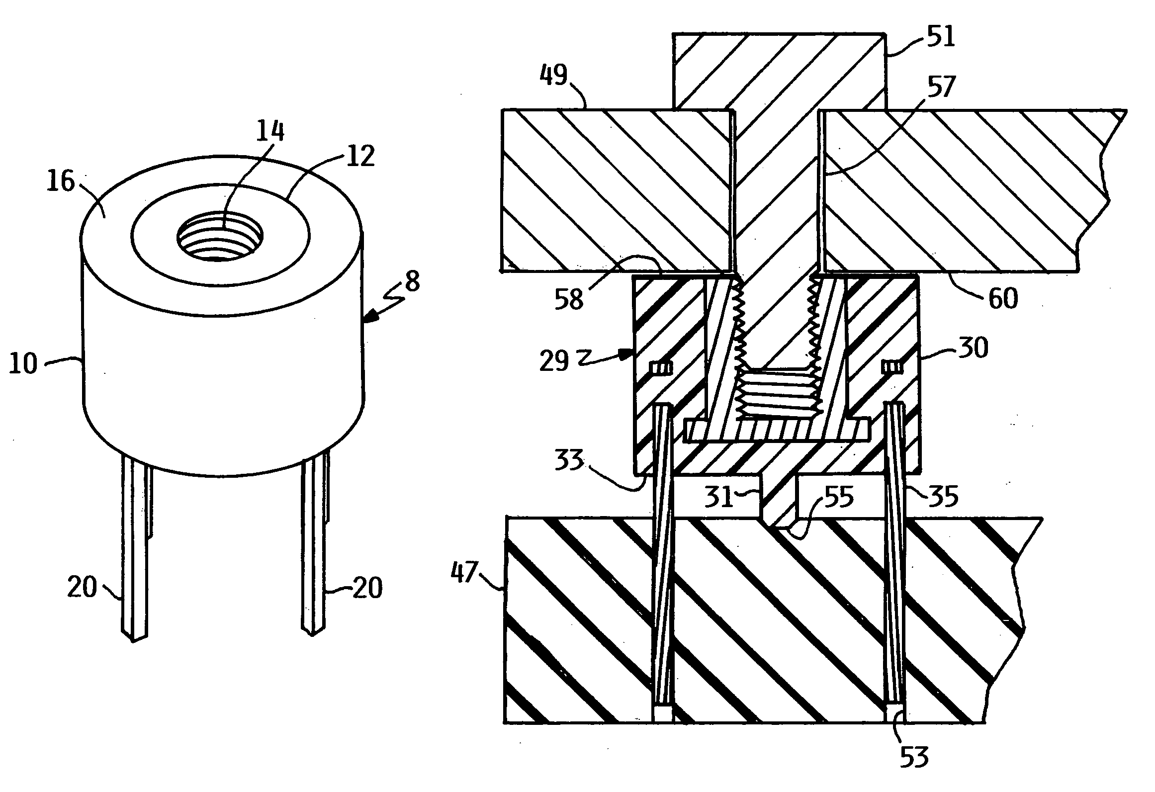
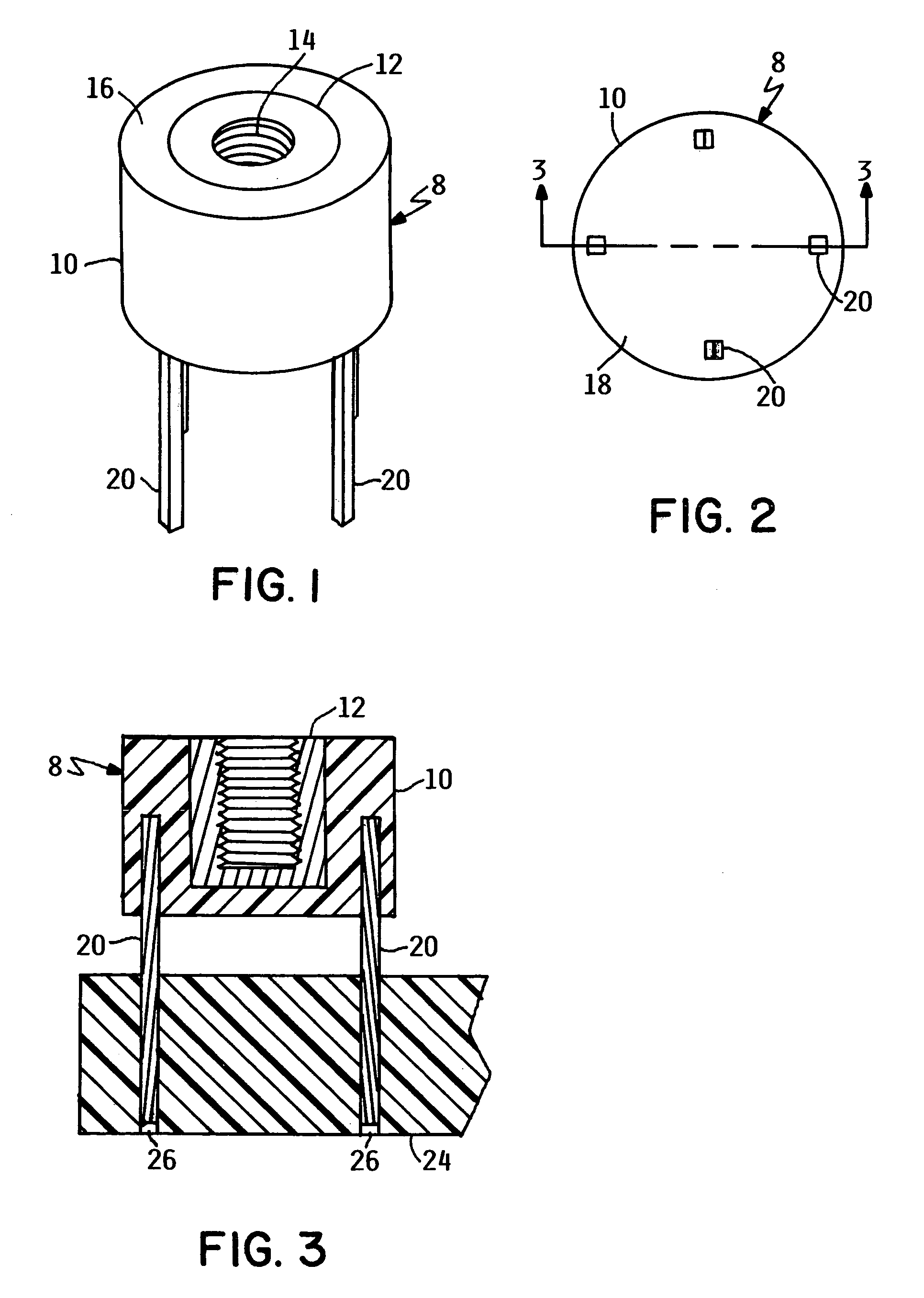
FIG. 1 is an isometric view illustrating the printed circuit board connector 8 of the present invention. FIG. 1 shows the molded polymer body portion 10 wherein a metal insert 12 is embedded or captured. The metal insert 12 is coaxial with body portion 10 and presents a threaded opening 14 which extends into the body portion from the upper surface 16. Projecting from the body portion lower surface 18 (visible in the bottom view of FIG. 2) are four pins 20 which are also embedded in and captured by the molded polymer body portion 10. These pins 20 are formed of rigid metal, are parallel to one another, and are symmetrically arranged radially outward of the metal insert 12.

The molded polymer body portion 10 may be formed of any polymer that possesses the required characteristics such as strength. An example of such a material that has been used and found satisfactory for the application is poly (ether imide).

FIG. 3 illustrates, in an axial section view through a pair of pins 20 and ...


PUM


Abstract

A connector for attaching a printed circuit board to other apparatus is formed as a separate connector body with a plurality of pins projecting from one end surface that are attached to the printed circuit board by being secured in vias through the board and a threaded opening at the end surface opposite the one end surface from which the pins project. When a bolt is received in the connector threaded opening and drawn tight to secure the printed circuit board to other apparatus, the stresses and material deformation induced by the securing bolt are isolated from the printed circuit board. Further, the attachment of the pins to the printed circuit board rather than the use of screws extending through holes in the circuit board reduces the size of ‘keep out’ zones that must be avoided by the wiring paths on each wiring surface of the printed circuit board through which mounting holes extend. Fabrication of the connector and assembly of the connector to the printed circuit board are facilitated by providing a pair of parallel side surfaces on the connector body which can be gripped by a tool. The connector can also be used to electrically insulate or provide a current path by the selection of the polymer that forms the connector body portion.

Description

FIELD OF THE INVENTION The present invention relates to connectors and more particularly to a connector structure for securing precision, high density apparatus such as multilayer circuit boards to a supporting structure. BACKGROUND OF THE INVENTION Connection techniques currently used for securing printed circuit boards to supporting structures are prone to subject the board to damage. The most frequently used method of printed circuit board mounting is to provide holes in the board through which attachment screws extend. Using this method, the screw head or the washer interposed between the screw head and the board is prone to compress and sometimes penetrate the circuit board causing shorting of wire traces, power planes or both. Further, the screw threads are apt to dig into the walls defining the circuit board holes and can also cause shorting. Finally, the nut or other material adjacent the threaded opening in which the screw is received at the other side of the circuit board ...

Claims


Application Information

Patent Timeline
Patent Type & Authority Patents(United States)
IPC IPC(8): H01R13/73
CPCH01R13/73H01R12/57H01R12/707H01R12/7052H01R12/7047
Inventor JENSEN, RANDALL SCOTTPEETS, MICHAEL T.
Owner IBM CORP
Why Eureka
Try Eureka