Ankle implant

a technology of implants and ankles, applied in the field of implants, can solve problems such as bone fractures and bone weakening, and achieve the effect of reducing pain

Inactive Publication Date: 2005-03-08
SHORT TIMOTHY J +1
View PDF10 Cites 55 Cited by
  • Summary
  • Abstract
  • Description
  • Claims
  • Application Information

AI Technical Summary

Benefits of technology

A principal object of this invention is to provide a novel ankle implant for insertion in the ankle joint of a patient with osteoarthritis, rheumatoid arthritis, trauma-related Arthritis, or avascular necrosis (ostenonecrosis) to enable the patient to recover full ordinary use of the ankle joint with no pain, or greatly reduced pain.

Problems solved by technology

This procedure requires resectioning a relatively large amount of bone, which may cause bone weakening and lead to bone fracture.

Method used


Image

  • Ankle implant
  • Ankle implant
  • Ankle implant

Examples


Embodiment Construction

Before explaining the present invention in detail it is to be understood that the invention is not limited in its application to the particular arrangement shown and described herein since the invention is capable of other embodiments. Also, the terminology used herein is for the purpose of description and not of limitation.

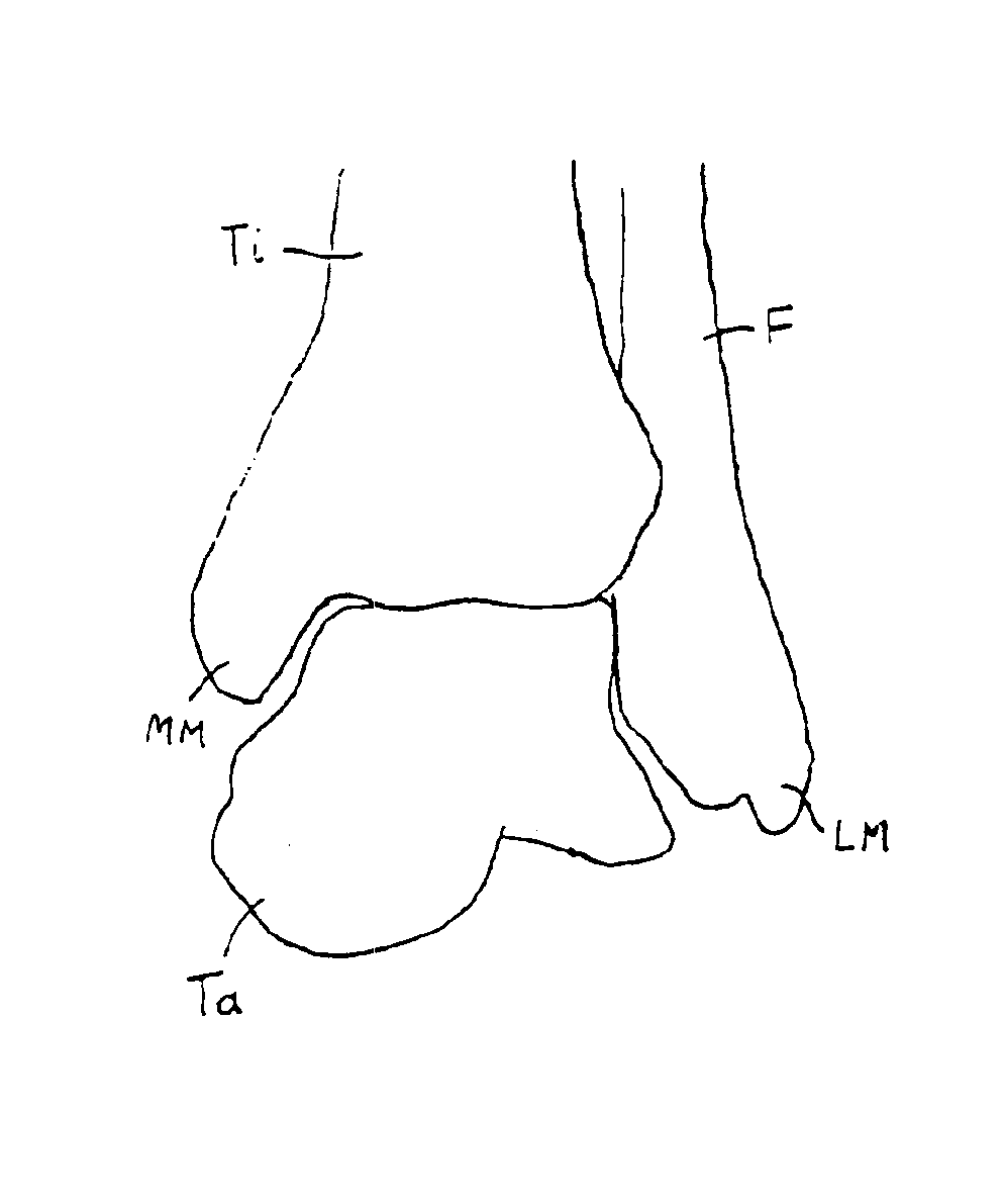
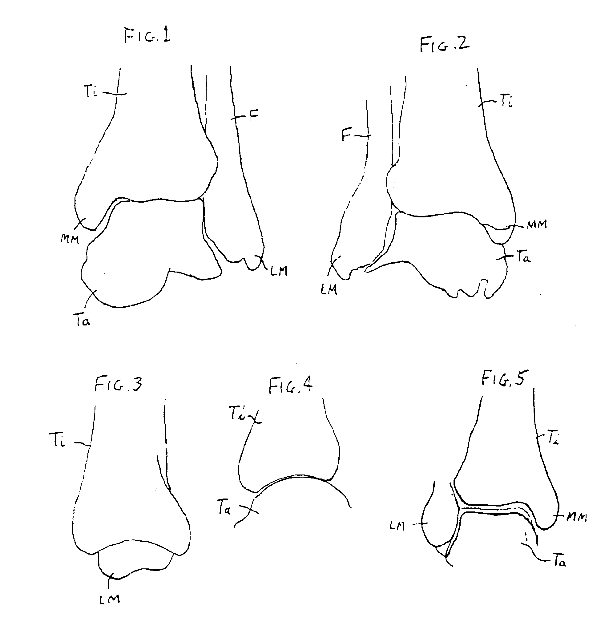
FIGS. 1-5 show various views of a person's tibia Ti, talus Ta and fibula F at the ankle joint. The medial malleolus of the tibia is designated MM, and the lateral malleolus of the fibula is designated LM.

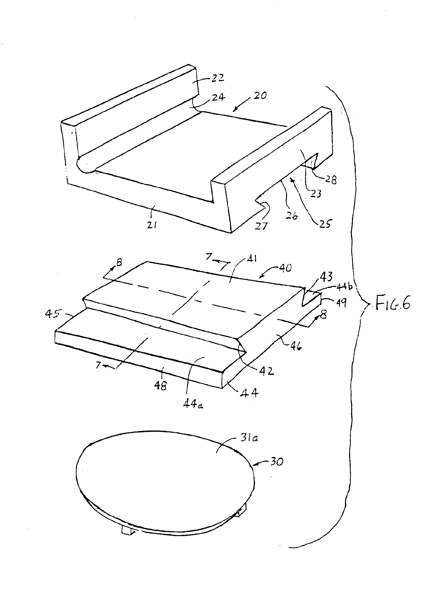
In accordance with the present invention, the ankle implant consists of a tibial component 20 (FIG. 6) for attachment to the lower end of the patient's tibia, a talar component 30 (FIGS. 6, 9, 10 and 11) for seating engagement in the top of the talus, and a bearing component 40 (FIGS. 6, 7 and 8) for attachment to the tibial component and sandwiched engagement between the tibial and talar components.

Referring to FIG. 6, the tibial component 20 of this implant is ...


PUM


Abstract

An ankle implant having a tibial component with a bottom groove, a talar component with a convex dome on top, and a bearing component slidably insertable into the bottom groove in the tibial component and having a concave bottom recess receiving the top dome of the talar component. The tibial component is channel-shaped, with a flat bottom wall for reception in a corresponding surgically prepared recess in the bottom of the patient's tibia, an anteriorly inclined posterior end wall projecting up from its bottom wall, a taller anterior end wall perpendicular to its bottom wall, and a rounded groove on the inside at the juncture between the anterior and bottom walls. The talar component has a cross-shaped segment on the bottom for reception in a corresponding surgically prepared recess in the top of the patient's talus.

Description

BACKGROUND OF THE INVENTION1. Field of the InventionThis invention relates to an implant for insertion between a person's tibia and talus to enable the ankle to function substantially normally and overcome or alleviate the effects of arthritis or avascular necrosis in the ankle joint.2. Prior ArtThe Buechel-Pappas Total Ankle Replacement System comprises:a tibial component with an upwardly-projecting fixturing stem that extends centrally up into the patient's tibia in the marrow region, and a bottom plate located just below the tibia and presenting a flat bearing surface on the bottom;a meniscus bearing component with a flat bearing surface at the top that slidably engages the tibial component plate from below, and a bottom bearing surface of compound curvature; anda talar component with a top bearing surface of compound curvature substantially complementary to that of the bottom surface of the bearing component, and a pair of downwardly-projecting fixation fins on the bottom for re...

Claims


Application Information

Patent Timeline
Patent Type & Authority Patents(United States)
IPC IPC(8): A61F2/42A61F2/00A61F2/30A61F2/46
CPCA61F2/4202A61F2/30771A61F2310/00023A61F2/4606A61F2002/30125A61F2002/30153A61F2002/30179A61F2002/30326A61F2002/30387A61F2002/30401A61F2002/30507A61F2002/30604A61F2002/3082A61F2002/30831A61F2002/30884A61F2002/30896A61F2002/4205A61F2002/4207A61F2002/4681A61F2220/0025A61F2230/0008A61F2230/0019A61F2230/0058A61F2250/0037
Inventor SHORT, TIMOTHY J.VO, HA VAN
Owner SHORT TIMOTHY J
Why Eureka
Try Eureka