Beam position monitoring for laser eye surgery

a laser eye surgery and position monitoring technology, applied in the field of laser eye surgery, can solve the problems of large laser system, complicated treatment protocols, and relatively high cost, and achieve the effect of inhibiting unwanted ablation and enhancing safety and success

Inactive Publication Date: 2005-03-08
AMO MFG USA INC
View PDF19 Cites 37 Cited by
  • Summary
  • Abstract
  • Description
  • Claims
  • Application Information

AI Technical Summary

Benefits of technology

The present invention provides methods, apparatus and systems for monitoring the position of a laser beam during laser eye surgery. Typically, the invention is used to verify that a desired scanning or adjustment of the laser beam across an eye is, in fact, occurring. Such monitoring and verification functions enhance the safety and success of laser eye surgery procedures. Generally, the invention includes a monitoring laser beam directed through a scanning mechanism at a sensor. When the scanning mechanism is adjusted, to scan an ablative laser beam across an eye, the scanning mechanism also scans the monitoring laser beam across the sensor. Changes in position of the monitoring beam sensed by the sensor can be used to measure scanning of the ablative beam across the eye. Such measured scanning may then be compared to a desired scanning pattern and, if the actual scanning does not match the desired pattern, the laser surgery system may shut down to halt the laser surgery procedure at least temporarily and inhibit unwanted ablation of the eye.

Problems solved by technology

This is typically relatively expensive, and leads to relatively large laser systems.
However, the use of such small beams complicates certain aspects of the treatment protocols required to perform the sculpting.
If the beam resides at one position for too long, due to a jam or malfunction of the scanning mechanism for example, the desired tissue ablation pattern may not be achieved.
A jam of the scanning system may jeopardize the success of the surgery and could cause damage to the patient's eye.
Since the laser beam itself is not easily visible, malfunction of some scanning mechanisms may not be readily detectable by an observer.

Method used


Image

  • Beam position monitoring for laser eye surgery
  • Beam position monitoring for laser eye surgery
  • Beam position monitoring for laser eye surgery

Examples


Embodiment Construction

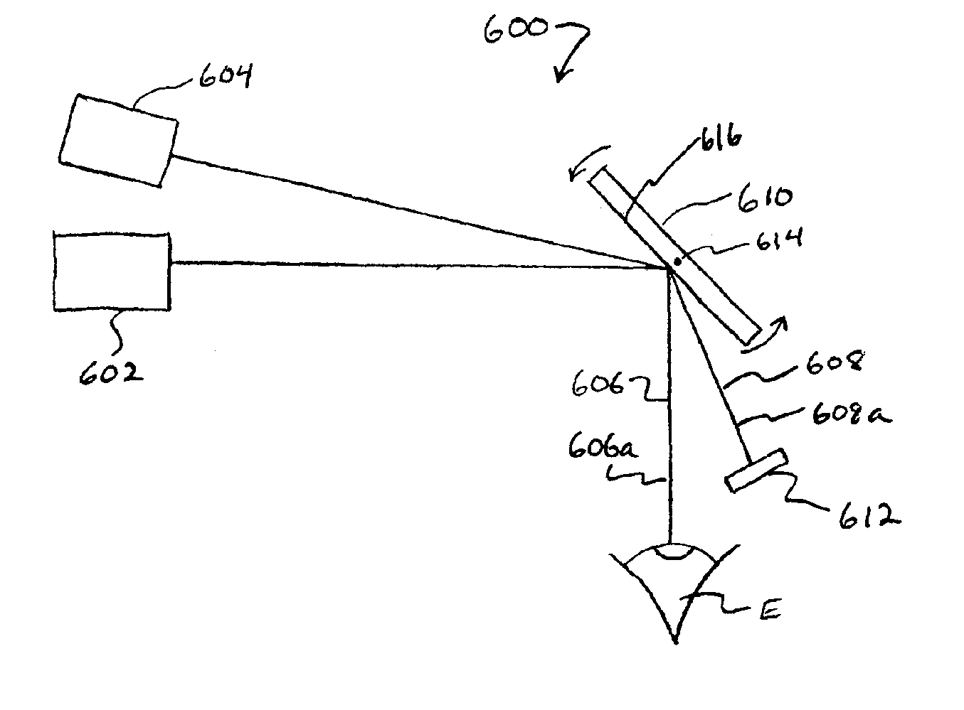
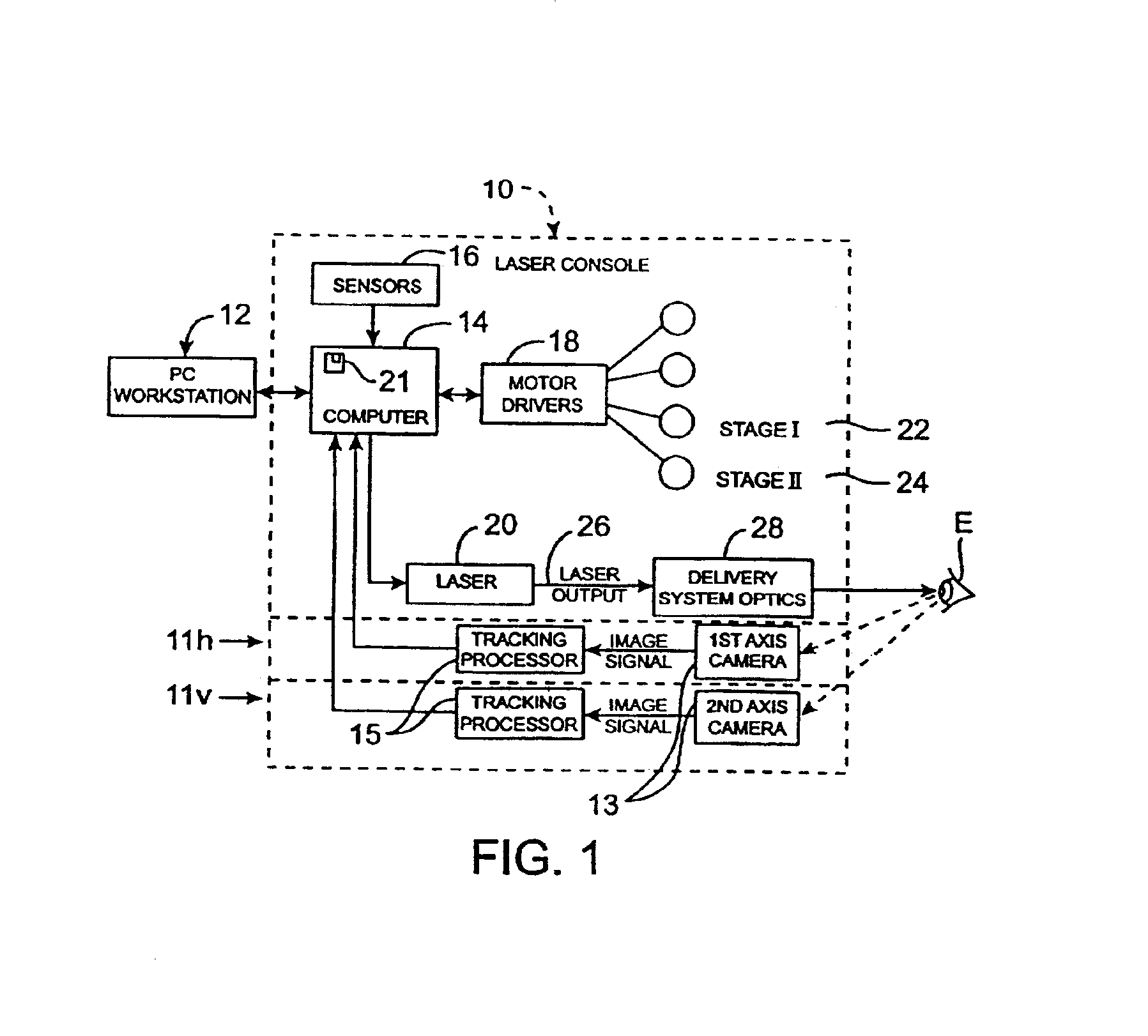
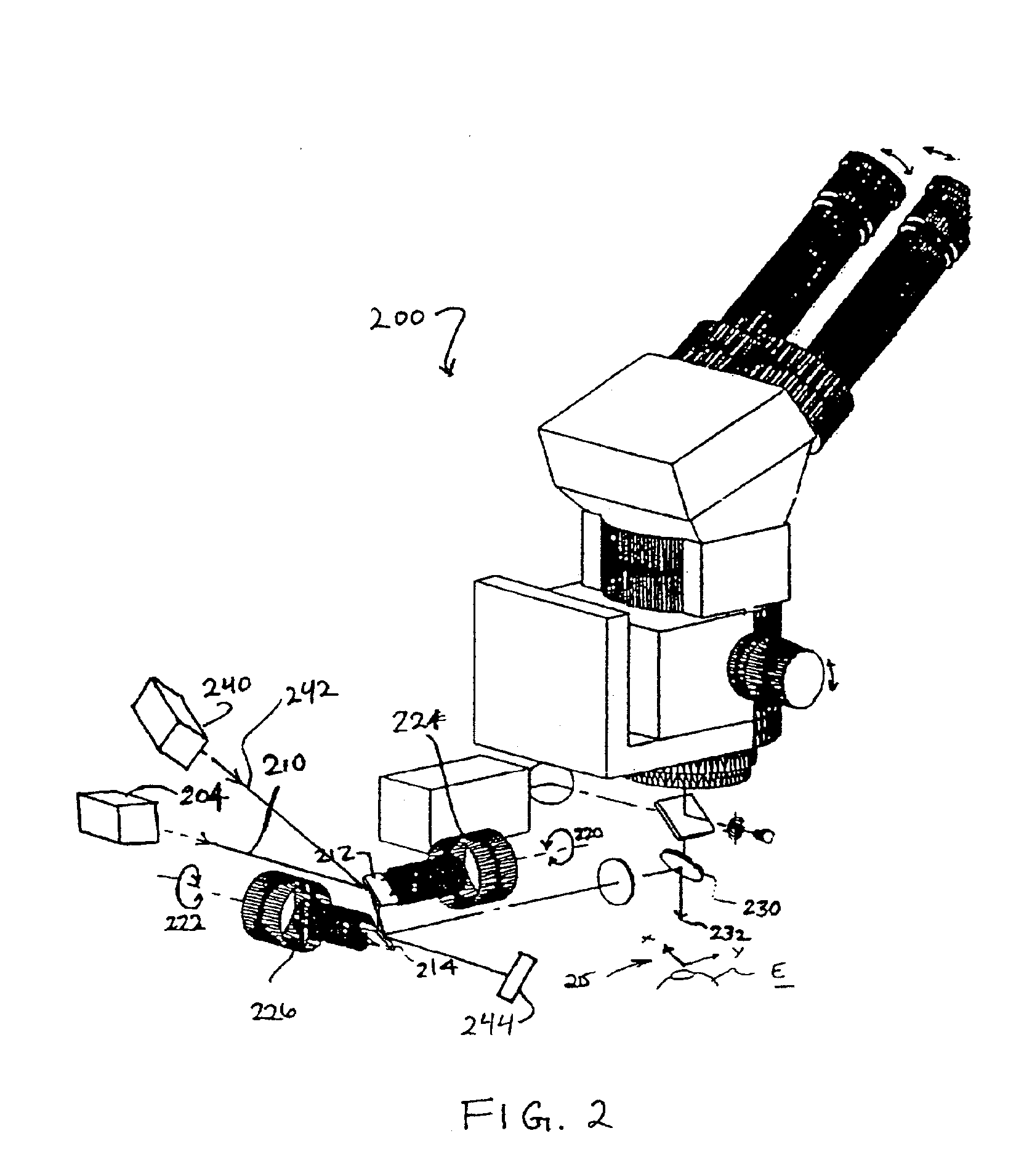
The present invention provides methods, apparatus and subsystems for monitoring laser beam position in laser eye surgery systems, particularly though not exclusively in laser eye surgery systems of the scanning type. In particular, the present invention provides monitoring methods and systems for verifying laser beam position during the course of corrective surgical ablation of an eye. By verifying that the ablative laser beam has moved to a position corresponding with a predetermined position dictated by a predetermined adjustment sequence or ablation pattern, the system can verify that mechanisms used to scan or move the beam from one position to a next position are functioning properly. This monitoring function enhances safety and efficacy of the laser surgery system by enabling the system to detect malfunctions in, for example, the scanning mechanism, and to interrupt the surgical procedure when an actual laser beam position does not correspond with a corresponding position dict...


PUM


Abstract

Improved methods, apparatus and systems for monitoring laser beam position enhance the safety and efficacy of laser eye surgery systems. The present invention will advantageously be used in laser eye surgery where accurate control of the laser beam is crucial for patient safety and successful vision correction. In one embodiment, a first beam of laser energy is directed through a scanning mechanism toward an eye to ablate the eye, and a second beam of laser energy is directed through the scanning mechanism toward a sensor. When the scanning mechanism is moved by a laser eye surgery system to move the first beam across the eye, the scanning mechanism also moves the second beam across the sensor. Movement of the beam across the sensor can be used to monitor movement of the first beam across the eye. If actual movement of the first beam across the eye does not match desired movement of the beam, one or more components of the laser surgery system will shut down in order to stop the laser eye surgery procedure, thus preventing undesirable ablation of the eye.

Description

BACKGROUND OF THE INVENTIONThe present invention relates generally to methods, apparatus and systems for performing laser eye surgery. More particularly, the present invention relates to laser beam position monitoring methods, apparatus and systems for enhancing safety of laser eye surgery systems.Photorefractive keratectomy (PRK) and phototherapeutic keratectomy (PTK) employ laser beam delivery systems for directing laser energy to a patient's eye to selectively ablate corneal tissue to reform or sculpt the shape of the cornea and, thereby, to improve vision. Present commercial systems often employ excimer lasers. In a first type of system, positioning of the beam is generally fixed and the beam has a cross-sectional area generally corresponding to an entire surface area of a surgical site on the cornea. Cross-sectional portions of the beam are then sequentially masked or adjusted so as to selectively vary the amount of energy exposure of different portions of the surgical site so ...

Claims


Application Information

Patent Timeline
Patent Type & Authority Patents(United States)
IPC IPC(8): A61F9/01A61F9/007G02B26/12
CPCA61F9/00804G02B26/127A61F9/00817A61F2009/00872A61F2009/00846
Inventor SCHRODER, RUSSELL
Owner AMO MFG USA INC
Why Eureka
Try Eureka