Fluid power generator

a technology of power generator and flue gas, which is applied in the direction of electric generator control, renewable energy generation, greenhouse gas reduction, etc., can solve the problem of excessive rotation of wind turbines

Inactive Publication Date: 2005-03-08
SEKI KAZUICHI
View PDF7 Cites 39 Cited by
  • Summary
  • Abstract
  • Description
  • Claims
  • Application Information

AI Technical Summary

Benefits of technology

In order to attain the above object, in accordance with this invention, there is provided a fluid power generator system comprising a generator coupled with a wing axial shaft which is rotated by operative fluid energy as a driving source and a load device including a battery connected to the generator, comprising a comparing means for comparing an measured tip speed ratio and a reference tip speed ratio, the measured tip speed ratio being calculated by a flow-rate signal based on a flow-rate of the operative fluid and a number of rotations signal based on the nu

Problems solved by technology

However, the moment that the output from the generator is short-circuited, the gene

Method used


Image

  • Fluid power generator
  • Fluid power generator
  • Fluid power generator

Examples


Embodiment Construction

Now referring to the drawings, an explanation will be given of an embodiment of this invention.

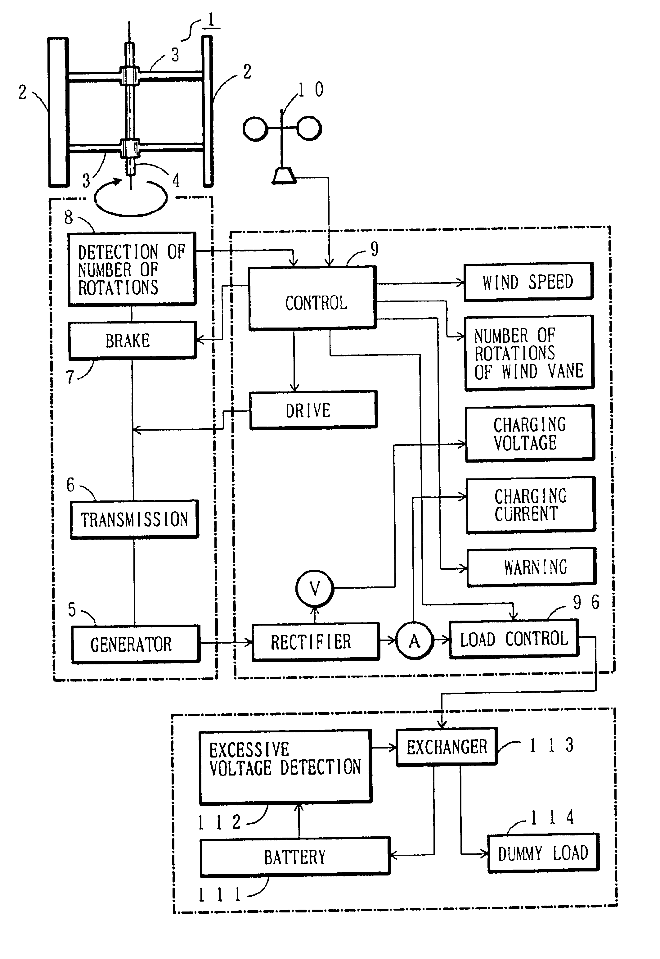
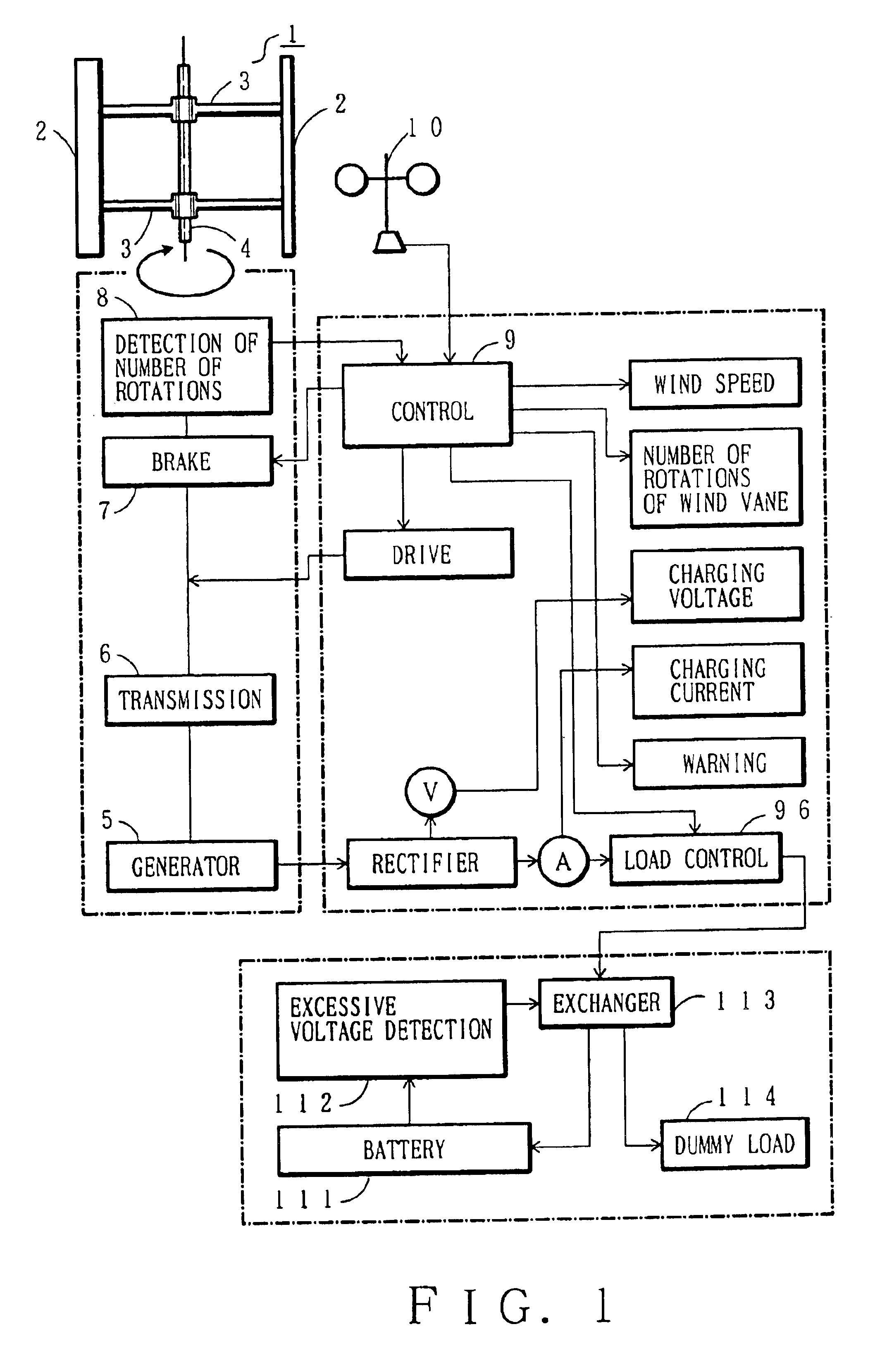
FIG. 1 shows an arrangement of the wind power generator which converts wind power energy serving as operative fluid energy into rotary energy to be used as electric energy;

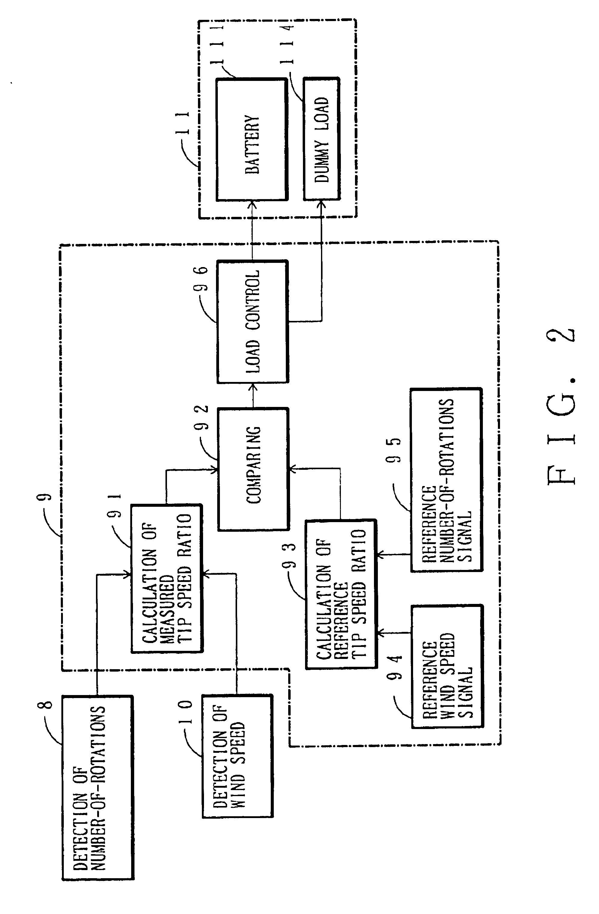
In FIG. 1, a wind turbine 1 includes e.g. linear blades 2 which are integrally attached to a wing axial shaft 4 by upper and lower supporting blades 3, respectively. The wing rotary shaft 4 is coupled with a generator 5 such as a synchronous generator (three-phase AC) through a transmission. The wing axial shaft 4 is provided with a brake 7 and a revolving number detecting unit 8 for the number of rotations of the wind turbine 1.

The revolving number detecting unit 8 serves to detect the number of rotations of the wind turbine 1 with the aid of a tachometer generator and a photosensor and photovoltaic converter. This detected number-of-revolution signal is supplied to a control circuit 9. The wind speed is detected by a w...


PUM


Abstract

In a fluid power generator system using operative fluid energy, a measured tip speed ratio and a reference tip speed ratio are compared with each other. If the measured tip speed ratio is smaller than the reference tip speed ratio, a generator is placed in a no-load state, thereby restoring the number of rotations of the wing axial shaft to the number of rotations corresponding to the reference tip speed ratio. Further, the operation of the generator is controlled on the basis of the tip speed ratio calculated from the flow rate of the fluid, thereby providing a maximum output for each flow rate. In this way, a change in the flow rate and number of rotations can be appropriately dealt with and the maximum output for each flow rate of the operative fluid can be dealt with, thereby increasing a quantity of generated power.

Description

TECHNICAL FIELDThis invention relates to a fluid power generator system for converting operative fluid energy such as wind into rotary energy to be used as electric energy.BACKGROUND ARTAs a fluid power generator system which uses the operative fluid energy as a driving source to generate electric power, a wind vane generator using wind power energy has been proposed. In the field of this wind vane generator, the wind power energy, a demand of using wind power energy in a wide range from a breeze to strong wind has been enhanced.The wind power generator system includes a generator which is driven by rotation of a wind turbine and a battery which is charged by power supply from the generator. In this wind power generator system, power can be supplied to loads such as an electric device while the battery is charged by the rotation of the wind turbine.In the above conventional wind power generator system, even when there is a breeze blowing, the generator which serves as load for the w...

Claims


Application Information

Patent Timeline
IPC IPC(8): F03D9/00F03D9/02F03D7/06F03D7/02F03D7/00F03D7/04H02P9/00
CPCF03D7/0272F03D7/06F03D9/021Y02E10/725F05B2270/32F03D9/007F03D9/11F03D9/25H02S10/12Y02E10/50Y02E10/72Y02E10/74Y02E70/30
Inventor SEKI, KAZUICHI
Owner SEKI KAZUICHI
Why Eureka
Try Eureka