Eureka AIR delivers breakthrough ideas for toughest innovation challenges, trusted by R&D personnel around the world.

Tidal Turbine System

a turbine system and variable pitch technology, applied in sea energy generation, tide stream/damless hydropower, electrical apparatus, etc., can solve the problems of supporting structure shifting, marginally less efficient turbines fitted with variable pitch blades, etc., to increase rotational speed, increase axial loading, and increase axial loading

Inactive Publication Date: 2011-10-20
TIDAL ENERGY
View PDF2 Cites 10 Cited by
  • Summary
  • Abstract
  • Description
  • Claims
  • Application Information

AI Technical Summary

Benefits of technology

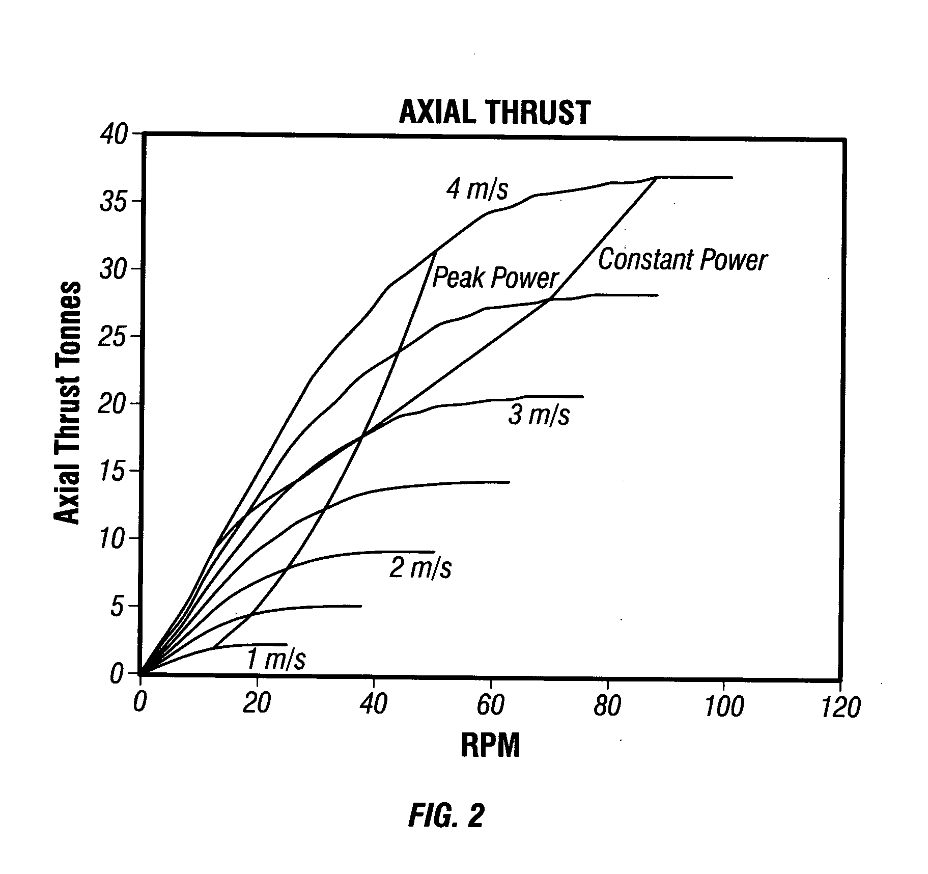
[0010]Beneficially, one or more parameters of the blade are selected or tailored to ensure that over the in-service operational speed range of the turbine, over a lower range of rotational speeds, increased rotational speed results in increased axial loading on the turbine, but at higher speed range above a predetermined threshold, axial loading on the turbine does not increase (or alternatively decreases).

Problems solved by technology

Turbines fitted with variable pitch blades are known to be marginally less efficient than those employing a fixed pitch at its best efficiency point.
Overloading could otherwise cause the supporting structure to shift on the seabed.

Method used


Image

  • Tidal Turbine System
  • Tidal Turbine System
  • Tidal Turbine System

Examples


Embodiment Construction

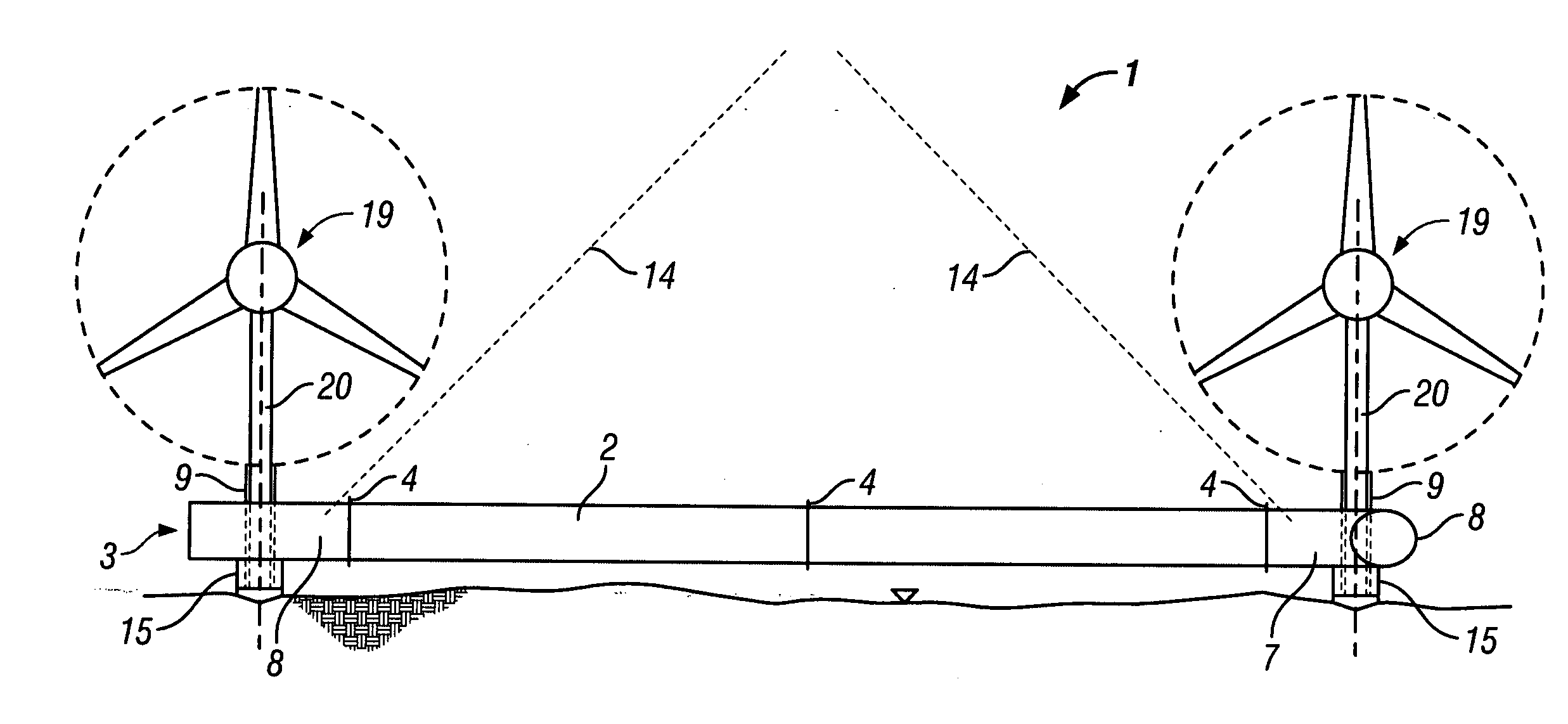
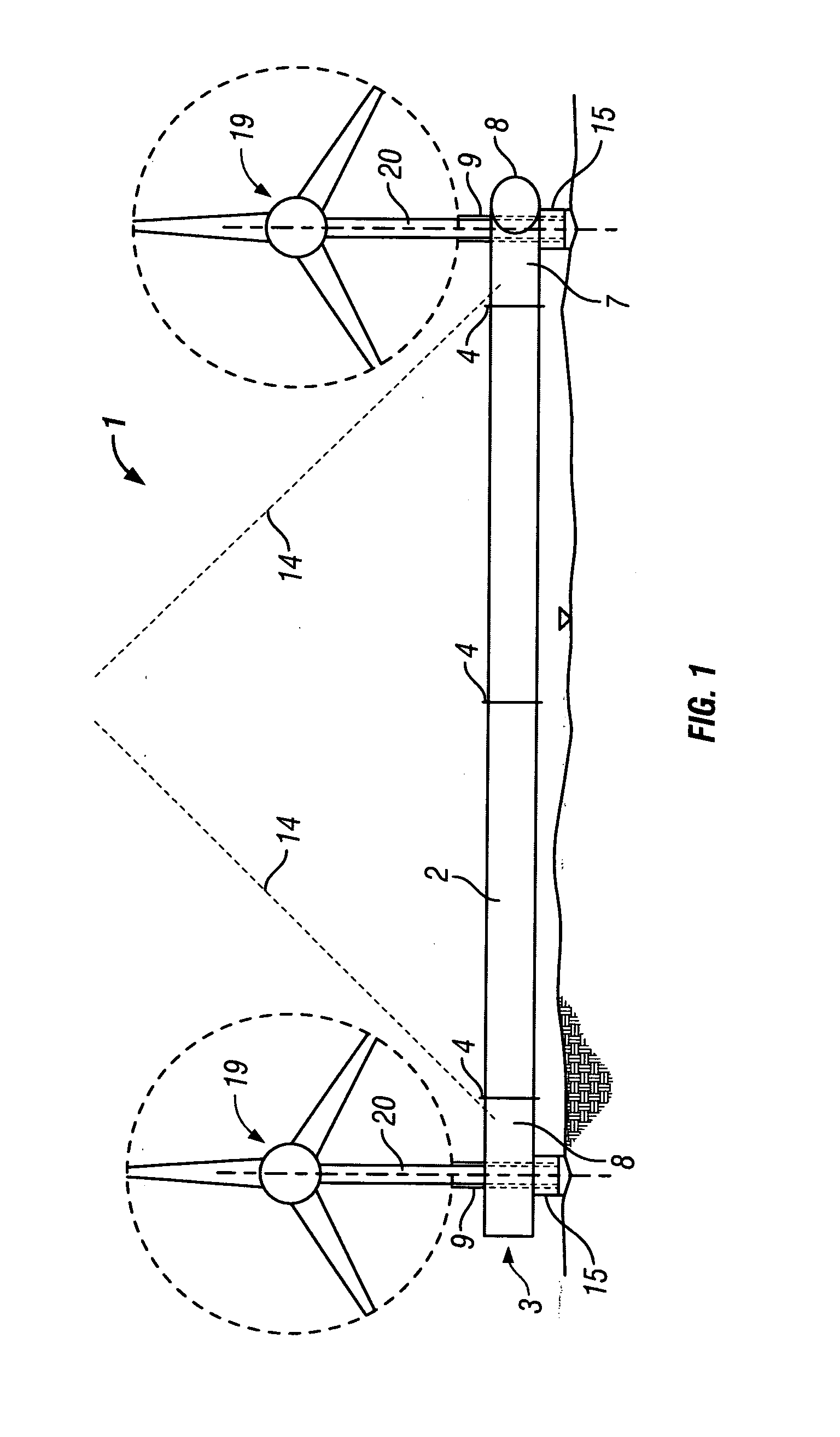
[0030]Referring to the drawings, and initially to FIG. 1 there is shown a tidal flow energy generation arrangement 1. The tidal flow energy generation arrangement 1 is required to be operated in extreme conditions. To be commercially competitive with other forms of power production areas of the seabed of high tidal flow energy concentration need to be utilised. These areas are difficult and dangerous to work in and the structure and its installation and retrieval need to take into account significant environmental hazards. The current flow, for example, is fast, typically upward of 4 Knots. Areas are often in deep water, which may be deeper than those in which a piling rig can operate. Storm conditions can cause costly delays and postponement. Tidal reversal is twice a day and the time between tidal reversal may be very short (for example between 15 and 90 minutes). Additionally, in such high tidal flow areas, the seabed is often scoured of sediment and other light material revealin...


PUM


Abstract

A tidal flow turbine system has a rotor and turbine blades attached at a fixed attitude with respect to the rotor and extending outwardly from the rotor. The stagger angle of the blades, tip speed ratio, or other blade parameters is such that over the in-service operational speed range of the turbine, over a lower range of rotational or tidal flow speeds, increased speed results in increased axial loading on the turbine, but at higher speed range above a predetermined threshold, axial loading on the turbine does not increase.

Description

[0001]The present invention relates to a tidal turbine system, particularly for use in a tidal flow energy generation system.BACKGROUND OF THE INVENTION[0002]Tidal energy is to a great extent predictable. At depths below significant wave effects the only basic changes in current flow are due the naturally occurring phases of the moon and sun. Superimposed on this pattern is a variation of flow velocities, some reaching a considerable fraction of the free-stream values, and which are due to intense atmospheric events.[0003]The deterministic nature of the availability of power, together with its high density and the implicit absence of visual impact makes tidal energy extraction a very attractive proposition particularly since virtually the whole of the available resources remain untapped.[0004]A number of tidal turbine schemes have been proposed with a division being between those which require the setting of sea floor foundations and those which do not. A free standing framework des...

Claims


Application Information

Patent Timeline
Patent Type & Authority Applications(United States)
IPC IPC(8): F03B13/26F03B13/18
CPCF03B13/264F03B17/061Y02E10/38F05B2240/97Y02E10/28F05B2240/95Y02E10/30F03B13/26F03B3/12F03B15/04Y02E10/20
Inventor FREEMAN, CHRISTOPHERWILLIAMS, CHRISTOPHER
Owner TIDAL ENERGY
Why Eureka
Eureka Blog
Learn More