Marine current power plant and a method for its operation

a technology of current power plant and rotor blade, which is applied in the direction of electric generator control, machines/engines, mechanical equipment, etc., can solve the problems of complex rotor blade holder required for this purpose, no possibility of decoupling from ambient flow of generic marine current power plant, and the control unit is a source of increased failure risk, etc., to achieve simplified bearings, high rotational speed, and high tip speed ratios.

Inactive Publication Date: 2014-05-01
VOITH PATENT GMBH
View PDF10 Cites 11 Cited by
  • Summary
  • Abstract
  • Description
  • Claims
  • Application Information

AI Technical Summary

Benefits of technology

[0016]As a result of the abrupt drop in the power coefficient of the water turbine upon occurrence of cavitation, down-regulation will already occur at relatively low tip speed ratios λ, so that lower centrifugal forces need to be caught in the revolving unit of the marine current power plant. As a result, relatively high tip speed ratios λ can be used, i.e. in the power-optimal operation with the power-optimal tip speed ratio λopt, thus leading to simplified bearing. Slide bearings can be used in particular. Furthermore, sufficiently high rotational speeds in power-optimal operation allow a compact electric generator.
[0017]Heavy inflow conditions, in which the water turbine revolves in the cavitation range, lead to high blade tip speeds. Sound is produced during the explosion of the cavitation bubbles which keeps marine life away from the rotor blades which revolve rapidly in this case. Furthermore, cavitation removes maritime growth on the rotor blades.

Problems solved by technology

Without the locking mechanisms that are typically provided in dam structures in the flow channels leading to the water turbine there is no possibility for decoupling from the ambient flow for generic marine current power plants in the case of an overload.
The rotatable rotor blade holder required for this purpose is complex from a constructional standpoint, especially for the large-size installations that are necessary for efficient power generation from currents that flow slowly.
Furthermore, the bearing components and actuators required for setting the blade angle as well as the relevant control unit represent a source of increased failure risk.
Since generic installations will typically be immersed completely, maintenance of the installation is difficult so that a simplified installation concept with rotor blades linked in a torsionally rigid manner will lead to an installation with a longer operational lifespan.
In this respect, the tip speed ratios used for down-regulation in strong inflow can lead to centrifugal forces which exert a strong load on the installation.

Method used


Image

  • Marine current power plant and a method for its operation
  • Marine current power plant and a method for its operation
  • Marine current power plant and a method for its operation

Examples


Embodiment Construction

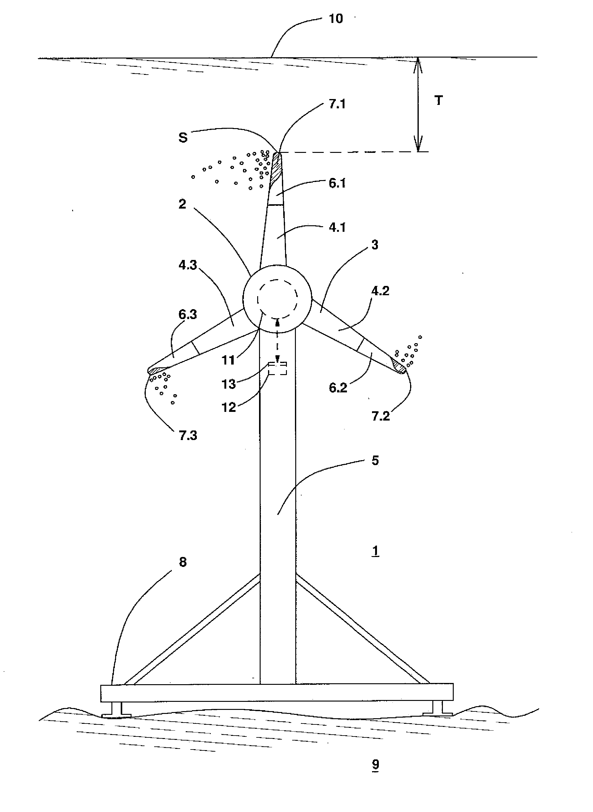
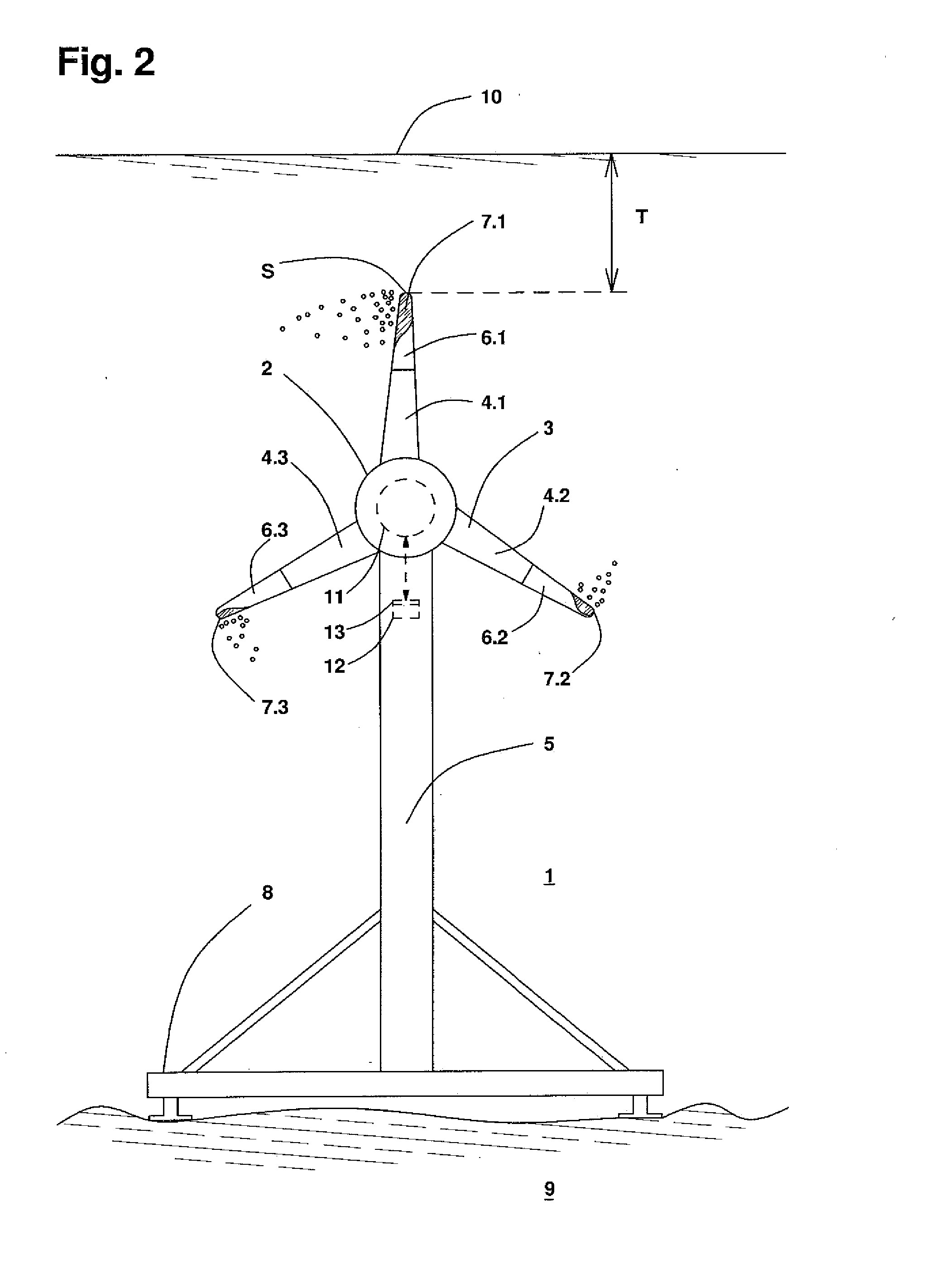
[0025]FIG. 2 shows a schematic simplified view of a marine current power plant 1 in accordance with the invention, which is supported on the ground 9 of a water body via a tower 5 and a gravity foundation 8. The marine current power plant 1 is completely situated beneath the water surface 10.

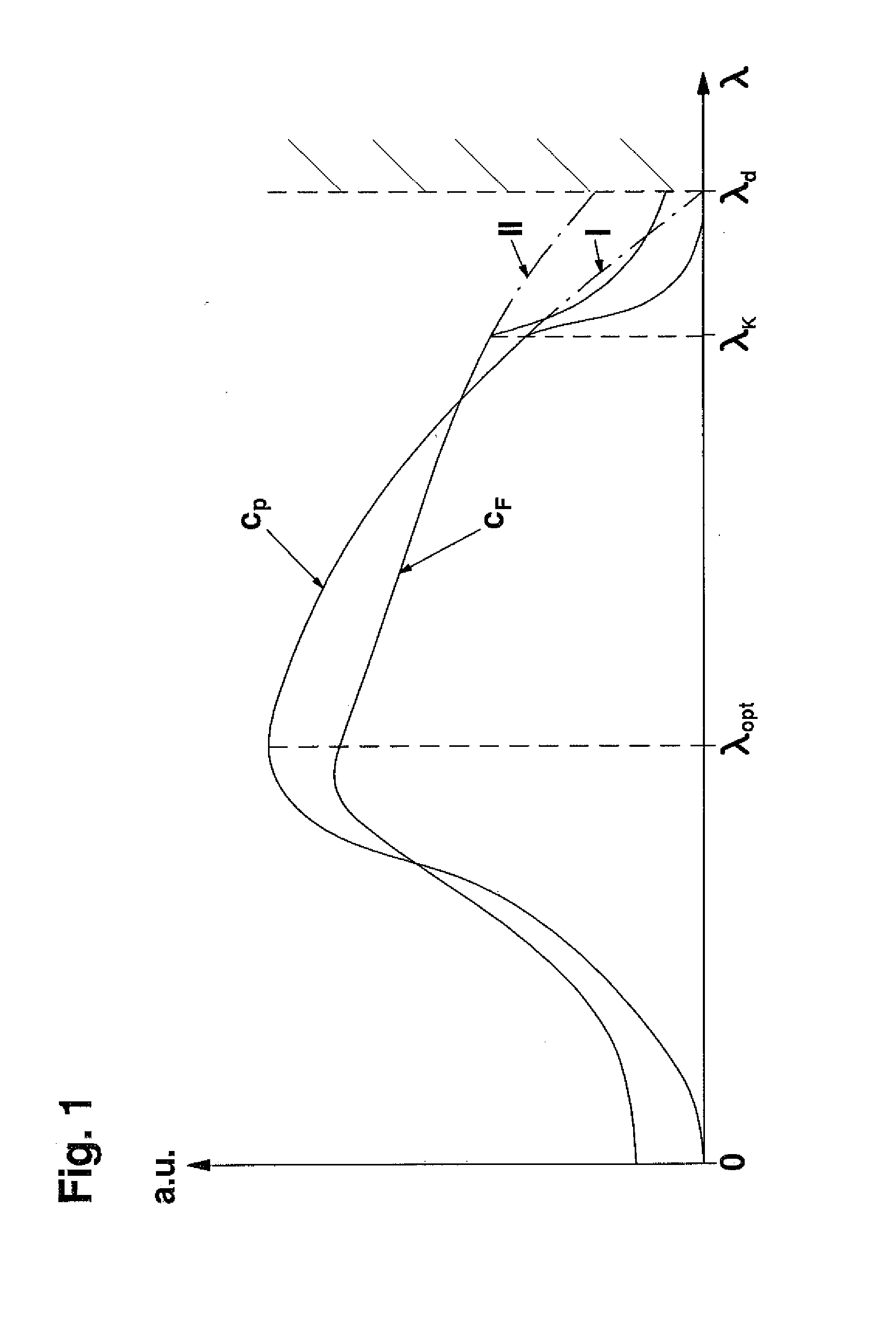
[0026]The revolving unit 2 of the marine current power plant 1 includes a propeller-shaped water turbine 3 with three rotor blades 4.1, 4.2, 4.3. Each rotor blade 4.1, 4.2, 4.3 includes on the radially outer half a cavitation-proof coating 6.1, 6.2, 6.3, which is arranged as an elastomeric coating. Furthermore, an electric generator 11 can be connected in a torsion-proof way to the water turbine 3. The electric generator 11 is associated with a control device 12 which is used for setting the generator torque. The speed guidance of the water turbine 3 occurs on the basis of a predetermined tip speed ratio λ. The control apparatus 12 includes load limiting means 13 for setting tip speed ratios λ u...


PUM


Abstract

The invention relates to a method for operating a marine current power plant, comprising a water turbine with several rotor blades arranged as buoyancy rotors, an electric generator which is driven at least indirectly by the water turbine, wherein the water turbine is guided for power limitation in an overspeed range above a power-optimal tip speed ratio. The water turbine is adjusted to the immersion depth of the marine current power plant in such a way that cavitation occurs on at least one rotor blade section in the overspeed range from a cavitation tip speed ratio threshold which lies below a tip speed ratio associated with a runaway speed, and the water turbine is operated for load limitation at tip speed ratios which lie above the cavitation tip speed ratio threshold.

Description

CROSS REFERENCE TO RELATED APPLICATIONS[0001]This is a continuation of PCT application No. PCT / EP2012 / 002764, entitled “A MARINE CURRENT POWER PLANT AND A METHOD FOR ITS OPERATION”, filed Jul. 2, 2012, which is incorporated herein by reference.BACKGROUND OF THE INVENTION[0002]1. Field of the Invention[0003]The invention relates to a marine current power plant which is especially used as a tidal power plant, and a method for its operation.[0004]2. Description of the Related Art[0005]Marine current power plants are known which comprise propeller-shaped water turbines arranged as buoyancy rotors combined with an electric generator, which are driven as freestanding units by the flow of a water body. An axial turbine design with a horizontal rotational axis is preferred in the present case. The use of such marine current power plants for power generation from a water course or a marine current can be considered at locations where no extensive barrages can be erected. A water turbine with...

Claims


Application Information

Patent Timeline
Patent Type & Authority Applications(United States)
IPC IPC(8): F03B13/10F03B15/00
CPCF03B13/10F03B15/00F03B11/04F03B13/264F05B2270/1095Y02E10/30F03B13/26F03B15/06F03B15/16F03B15/18F03B17/06Y02E10/20
Inventor HOLSTEIN, BENJAMINPERNER, NORMAN
Owner VOITH PATENT GMBH
Why Eureka
Try Eureka