Stirring heating device capable of tracking maximum wind energy utilization rate

A utilization rate and heating device technology, which is applied in the field of stirring heating devices, can solve the problems of reduced wind energy utilization efficiency, deviation of operation performance, and poor self-starting performance, so as to improve wind energy utilization efficiency, improve space utilization, and improve operation reliability effect

Active Publication Date: 2018-08-24
NORTHEAST DIANLI UNIVERSITY
View PDF7 Cites 11 Cited by
  • Summary
  • Abstract
  • Description
  • Claims
  • Application Information

AI Technical Summary

Problems solved by technology

[0005] 1) Existing wind energy stirring and heating devices generally have a working wind speed range of 7-35m/s, and a rated wind speed range of 13-15m/s, and can only be guaranteed to operate at the best tip speed ratio when operating at the rated wind speed , to ensure its maximum wind energy utilization efficiency, while in the rest of the wind speed range, the operating performance deviates seriously from the optimal tip speed ratio, resulting in a greatly reduced wind energy utilization efficiency when it operates at non-rated wind speeds;
[0006] 2) The self-starting performance of the existing wind energy stirring and heating devices is poor at low wind speeds, resulting in a serious narrowing of the wind speed utilization range. Therefore, the wind energy stirring and heating devi

Method used


Image

  • Stirring heating device capable of tracking maximum wind energy utilization rate
  • Stirring heating device capable of tracking maximum wind energy utilization rate
  • Stirring heating device capable of tracking maximum wind energy utilization rate

Examples


Example Embodiment

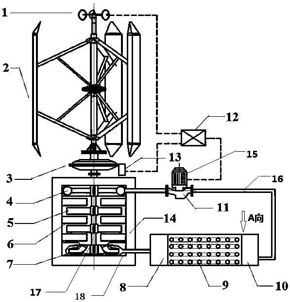
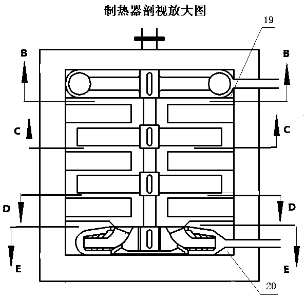
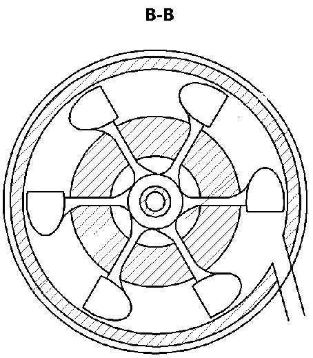
[0036] The following combination Figure 1-Figure 8 The present invention is further described in detail with specific embodiments, and the specific embodiments described here are only used to explain the present invention, not to limit the present invention.

[0037] Reference Figure 1-Figure 8 , According to a stirring heating device for tracking the maximum utilization rate of wind energy of the present invention, the wind cup type wind speed sensor 1 is installed on the top of the lift-type H-shaped vertical axis wind turbine 2, and the lower end of the lift-type H-shaped vertical axis wind turbine 2 is fixed Connected to the upper end of the planetary gearbox 3, the planetary gearbox 3 is the speed change mechanism, the lift type H vertical axis wind turbine 2 output shaft is connected to the planetary gearbox 3 input shaft, the laser speed sensor 13 is fixedly connected to the planetary gearbox 3 , The lower end of the planetary gear transmission 3 is fixedly connected to...


PUM


Abstract

The invention discloses a stirring heating device capable of tracking the maximum wind energy utilization rate. The stirring heating device comprises a wind turbine, a gearbox, a heating device, a circulating pump, a heat exchanger and a stirring working medium. The stirring heating device is characterized in that signals collected by a wind speed sensor and a rotation speed sensor are input to aprogrammable logic controller (PLC) to be processed, then, output signals control a motor to drive the circulating pump, and the stirring working medium is conveyed from the heat exchanger to the heating device; the rotation speed of the wind turbine under the operation working condition is adjusted in real time, the utilization section of the wind speed is broadened, the wind turbine can operateat the optimal tip speed ratio under various wind speeds, and the maximum wind energy utilization rate is achieved through the wind energy stirring heating device; and the wind energy resource is effectively utilized, and the stirring heating device has important theoretical and engineering practical significance to sufficient and efficient wind energy utilization and has wide commercial prospects.

Description

technical field [0001] The invention relates to a direct heating device using wind energy, in particular to a stirring heating device tracking the maximum utilization rate of wind energy. Background technique [0002] In the context of the depletion of traditional fossil energy and the increasingly serious environmental pollution, based on the fact that wind energy resources are abundant and belong to clean energy, it has been highly concerned by the national energy technology department. Due to poor wind power, the phenomenon of wind abandonment is very serious. Therefore, in recent years, wind energy heating devices that can directly convert wind energy into heat energy and can directly supply heat have been highly valued by scientific researchers and technicians. [0003] The wind energy direct heating device is a wind energy direct utilization technology that directly converts the kinetic energy of the wind into mechanical energy through the wind turbine, and then furthe...

Claims


Application Information

Patent Timeline
IPC IPC(8): F03D9/22F03D15/00F03D7/06F24V50/00F28D7/08
CPCF03D7/06F03D9/22F03D15/00F28D7/082Y02E10/72Y02E10/74
Inventor 姜铁骝张仲彬李博王艳红曹丽华金韦辰张立栋张毅胡鹏飞陈奇成宋粉红
Owner NORTHEAST DIANLI UNIVERSITY
Why Eureka
Try Eureka