
Low Reynolds Number Airfoil for a Wind Turbine Blade and Method Thereof

a wind turbine and airfoil technology, applied in the direction of wind turbines, wind motors, machines/engines, etc., can solve the problems of reducing the efficiency of wind turbines working under low wind speed conditions, degrading the lift characteristics of normal airfoils, and delay in starting

Active Publication Date: 2018-05-17
UNIVERSITI BRUNEI DARUSSALAM
View PDF0 Cites 11 Cited by
  • Summary
  • Abstract
  • Description
  • Claims
  • Application Information

AI Technical Summary

Benefits of technology

This patent is about a new design for wind turbine blades that can optimize their shape to capture more energy from wind. The design has a specific shape with a camber (a curved shape) and a thickness that are optimized for wind speed and power generation. The design also takes into account the location of the blade and the speed of the wind when it passes through the blade. By adjusting these features, the new blade design can improve the performance and efficiency of wind turbines.

Problems solved by technology

With regard to wind turbine blades, the poor lift characteristics of conventional airfoils at low Reynolds numbers delay the starting and reduce the efficiency of wind turbines working under low wind speed conditions.
However, under low Reynolds number conditions, lift characteristics of normal airfoils are degraded due to the formation of laminar separation bubbles.
The separation bubble thickens the boundary layer and thus increases the drag of the airfoil.
This device is less sensitive to changes in angle of attack, but causes larger additional drag.
However, these extra fittings over the airfoil surface may create undesirable disturbances to the flow.

Method used


Image

  • Low Reynolds Number Airfoil for a Wind Turbine Blade and Method Thereof
  • Low Reynolds Number Airfoil for a Wind Turbine Blade and Method Thereof
  • Low Reynolds Number Airfoil for a Wind Turbine Blade and Method Thereof

Examples


Embodiment Construction

[0024]The following description with reference to the accompanying drawings is provided to assist in a comprehensive understanding of exemplary embodiments of the invention as defined by the claims and their equivalents. It includes various specific details to assist in that understanding but these are to be regarded as merely exemplary. Accordingly, those of ordinary skill in the art will recognize that various changes and modifications of the embodiments described herein can be made without departing from the scope and spirit of the invention. In addition, descriptions of well-known functions and constructions are omitted for clarity and conciseness.

[0025]The terms and words used in the following description and claims are not limited to the bibliographical meanings, but, are merely used by the inventor to enable a clear and consistent understanding of the invention. Accordingly, it should be apparent to those skilled in the art that the following description of exemplary embodime...


PUM


Abstract

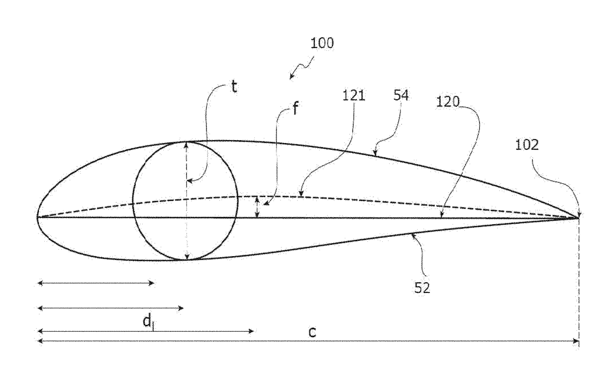
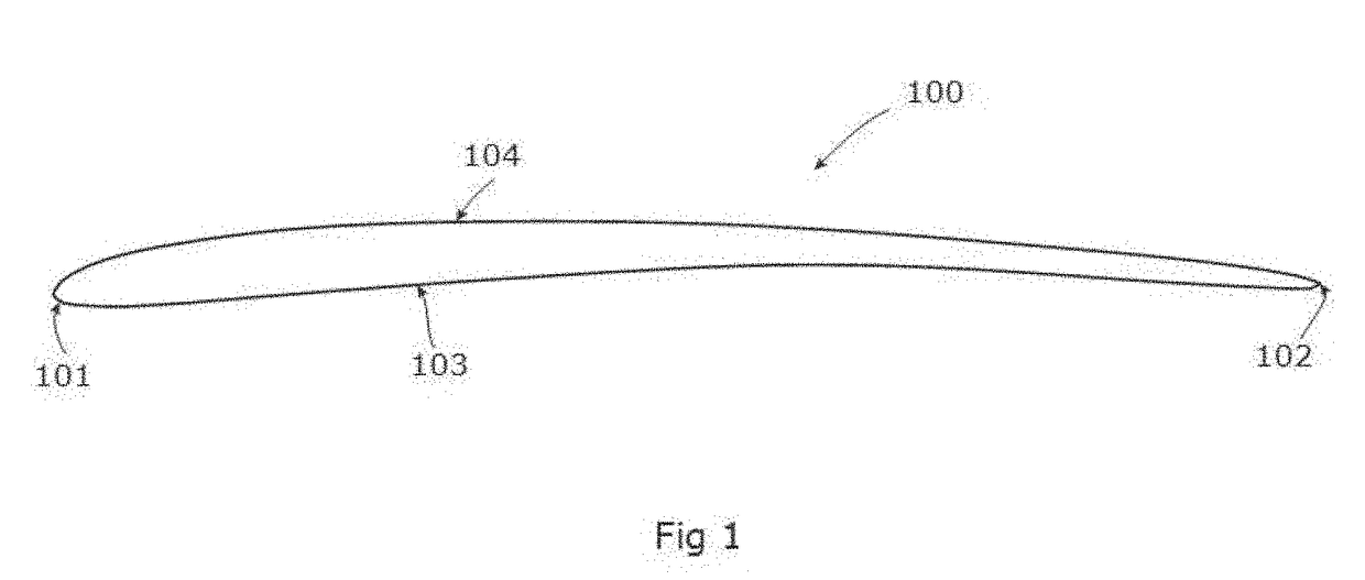
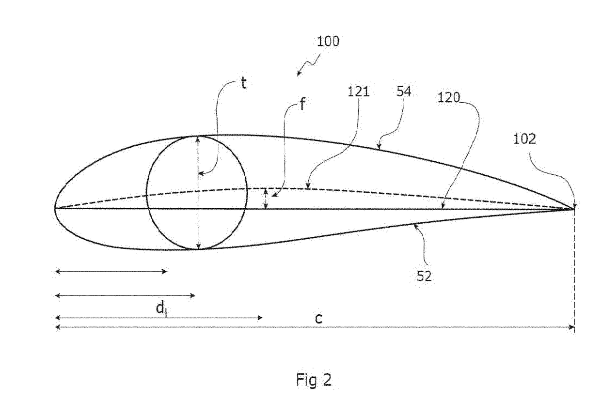
A low Reynolds number airfoil for a wind turbine blade, the airfoil having a leading edge 101, a trailing edge spaced from the leading edge 101, a chord 120 defined as a straight line joining the leading edge 101 and the trailing edge, a chord 120 length defined as distance between the trailing edge and the point on the leading edge 101 where the chord 120 intersects the leading edge 101 wherein the airfoil comprises a camber 121 between 5% to 7% of the chord 120 length, the camber 121 is disposed within a distance of 17% of the chord 120 length from the leading edge 101 and a thickness of the airfoil not greater than 7% of the chord 120 length. In an embodiment, it discloses A method of designing blade for low wind speed turbine for a site location, the method comprising obtaining time series data for the site location, computing a Weibull shape factor (K) and scale factor (C)corresponding to a Weibull distribution function based on the time series data for the site location, using K and C to identify energy intensive wind speed at the site location, determining blade length based on the energy intensive wind speed, K, C, a design power (PD) of the turbine, a design power coefficient (Cpd), and a density of the air (Ro), wherein the rated power of the turbine depends on load to be connected of the turbine, selecting a generator for use with the turbine, computing a design tip speed ratio based on a rated speed of the generator (NGD), a gear ratio (GR), the design power (PD), K, and C, identifying number of blades (B) depending on the design tip speed ratio and an end-use of the power being produced by the turbine; and identifying a chord 120 length and twist of the blade from root-to-tip.

Description

CROSS REFERENCE TO RELATED APPLICATIONS[0001]The instant application claims priority to U.S. Provisional Patent Application 62 / 154,203 filed on Apr. 29, 2015 and International PCT Application PCT / IB2016 / 052426 filed on Apr. 29, 2016. The pending U.S. Provisional Patent Application 62 / 154,203 and International PCT Application PCT / IB2016 / 052426 are hereby incorporated by reference in its entireties for all of its teachings.TECHNICAL FIELD[0002]The present invention relates to wind turbine blade technology and a method of designing a rotor blade. More particularly, the present invention relates to a rotor blade of wind turbine comprising a particular shape to minimize effect of laminar separation flow bubble without the need of a controller and a method to design a blade of a wind turbine with respect to the location of installation.BACKGROUND OF THE INVENTION[0003]Wind mills are assisting mankind to convert wind energy into electrical energy. Modern wind turbines are capable to conver...

Claims


Application Information

Patent Timeline
Patent Type & Authority Applications(United States)
IPC IPC(8): F03D1/06
CPCF03D1/0641F03D1/0633Y02E10/72
Inventor SHAH, HASEEBMATHEW, SATHYAJITHLIM, CHEE MING
Owner UNIVERSITI BRUNEI DARUSSALAM
Learn More