System for remotely adjusting antennas

Inactive Publication Date: 2005-03-08
WENSINK JAN BLAIR
View PDF9 Cites 9 Cited by
  • Summary
  • Abstract
  • Description
  • Claims
  • Application Information

AI Technical Summary

Benefits of technology

This invention addresses the disadvantages of current equipment and techniques, and provides the industry with an economical and efficient method of making remote P-L and CH adjustments of multi-antenna sectors typically found at cellular telephone networks.
In a typical cellular telephone network, base station performance deteriorates quickly due to over coverage and under coverage. It is the objective of this invention to provide a method and a hardware/software system to effectively optimize cellular network antennas by remotely adjusting antenna P-L and CH to eliminate over coverage and under coverage.
Antenna adjustments that are referenced to the support structure such as Singer are subject to many errors caused by weather, ground shifting, or disturbances due to the measurement process itself. Once the reference is flawed, then all the measurements based on that reference become corrupted. It is the objective of this invention to provide measurements and adjustments of down-tilt and azimuth that are made with respect to absolute geodetic measurements of P-L and CH.
Antenna site

Problems solved by technology

In a typical cellular telephone network, base station performance deteriorates quickly due to over coverage and under coverage.
Antenna adjustments that are referenced to the support structure such as Singer are

Method used


Image

  • System for remotely adjusting antennas
  • System for remotely adjusting antennas
  • System for remotely adjusting antennas

Examples


Embodiment Construction

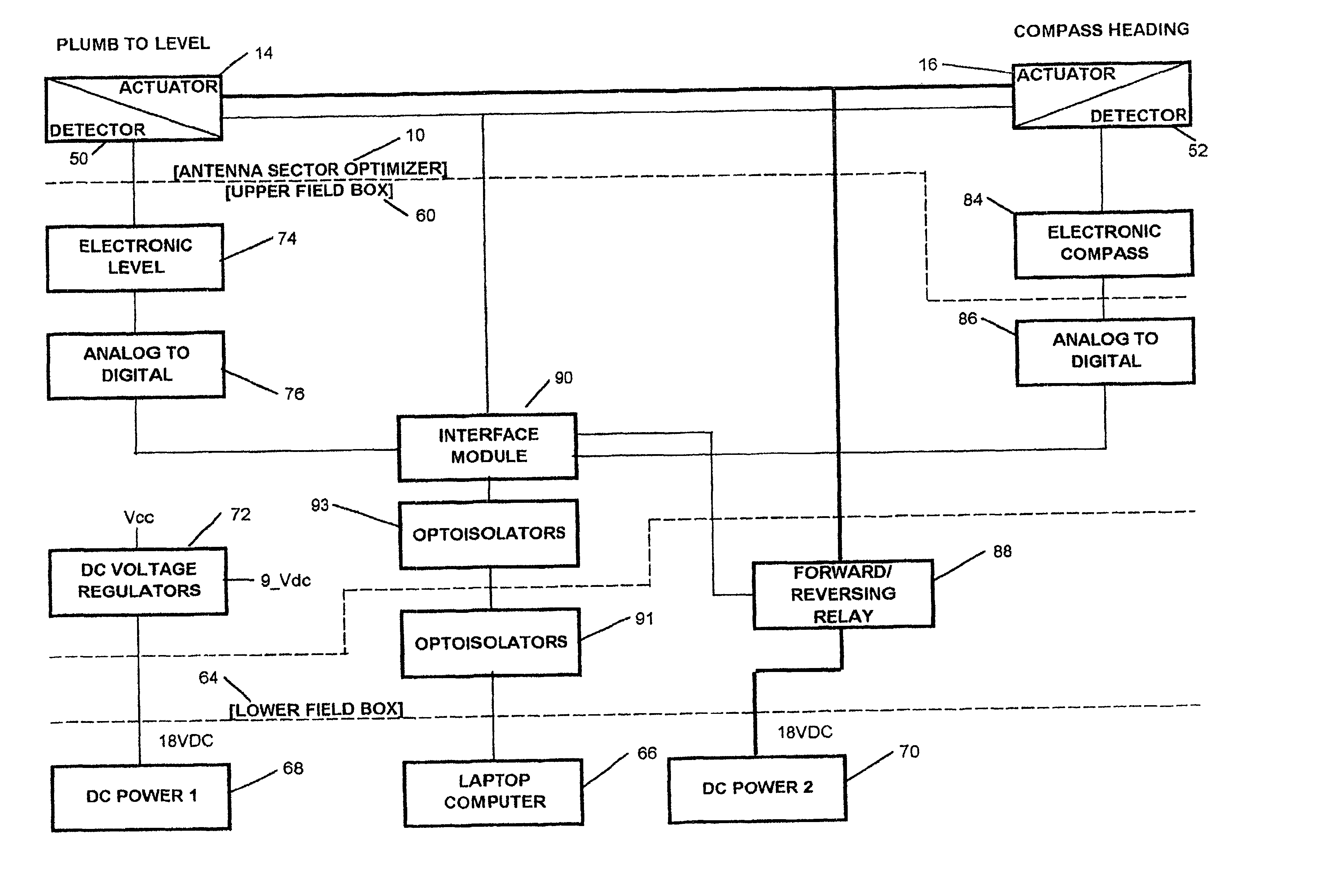
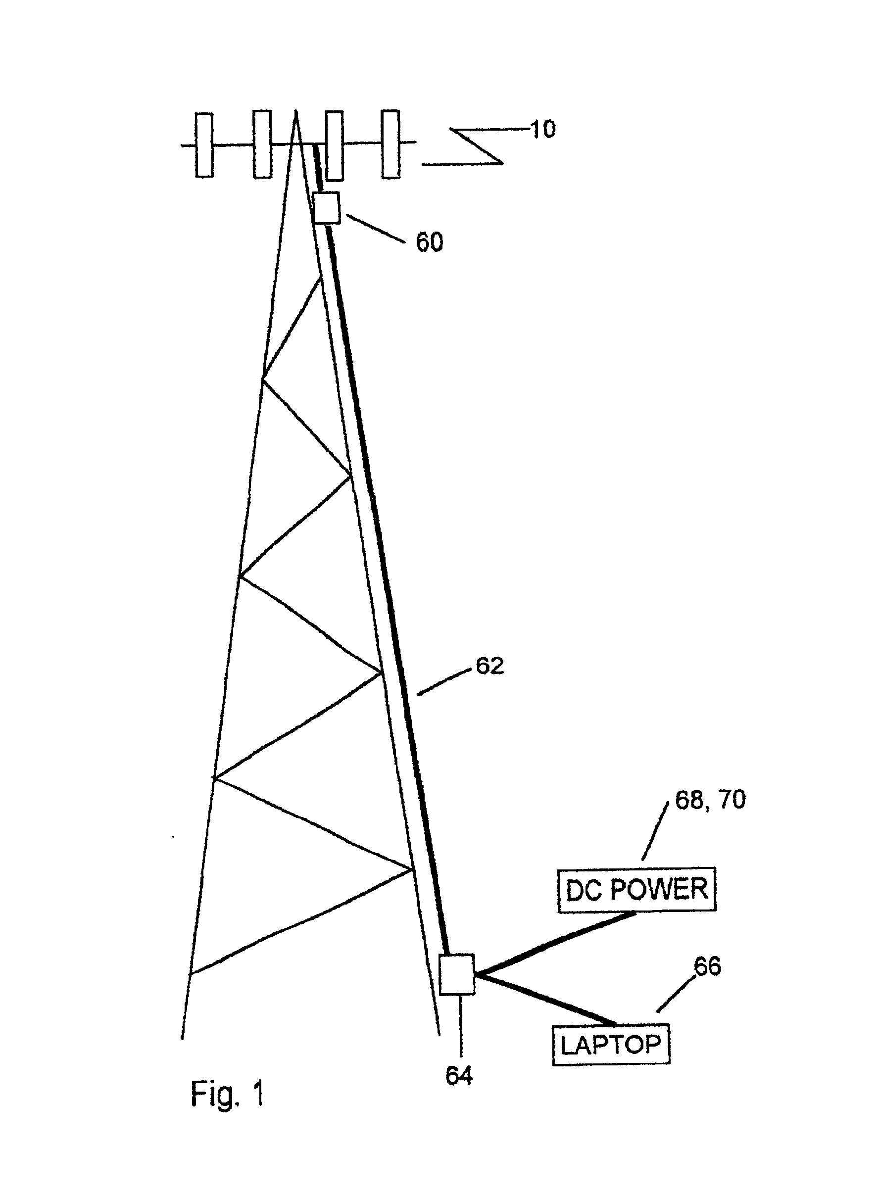
FIG. 1, shows a communications antenna system having, typically, four duplex transmitting and receiving cellular antennas mounted as a sector atop a suitable structure such as, for example, a tower. Furthermore, each cellular system tower may have up to three such sectors, each sector covering a segment that is usually ⅓ of a circle (120°). Referring to FIG. 1, a system for remotely adjusting the P-L and CH of one or a plurality of communication antennas, the subject of this invention is shown comprising: an antenna sector optimizer 10, mounted atop a tower, one or more weatherproof field interconnection boxes 60 and 64, an interconnection cable 62 running between the field boxes, one or more DC power sources 68 and 70, and a laptop computer 66. Although four antennas are shown to represent a sector in FIG. 1, this is not intended to be a limitation in scope, as one or a plurality of antennas may comprise a sector as defined by this invention. It is within the scope of contemplation...


PUM


Abstract

This invention describes a method, an apparatus, and a system for optimizing antenna performance by remotely adjusting the plumb-to-level (absolute measurements with respect to true vertical) and the compass heading (absolute compass heading direction with respect to magnetic North) of one or a plurality of communication antennas by electromechanical means. Until now, only fixed, manual adjustments referenced to points on the tower that are assumed to be accurate, but are not, can be made. Furthermore, antenna optimization that is accomplished by solely adjusting the tilt of an antenna is limited. And, since azimuth adjustments for antenna sectors are difficult to adjust manually and are not available by electromechanical means, site planning personnel have not been able to accurately compensate for changes in tower and site parameters. Also, since site surveys provide plumb-to-level and compass heading information, this invention allows remote adjustments of site parameters with absolute reference to survey data. Furthermore the invention allows antennas within a sector having antennas with capacity to spare to be swept into a sector experiencing higher traffic loads.

Description

CROSS REFERENCE TO RELATED APPLICATIONSNoneSTATEMENT REGARDING FEDERALLY SPONSORED R & DNoneREFERENCE TO A “MICROFICHE APPENDIX”NoneBACKGROUND OF THE INVENTION1. Field of the InventionThis invention describes a method, an apparatus, and a system for remotely adjusting by mechanical and electronic means the plumb-to-level and the compass heading of one or a plurality of communication antennas. The term plumb-to-level will be used throughout this description to represent absolute measurements with respect to true vertical. And, the term compass heading will be used throughout this description to represent absolute compass heading direction with respect to magnetic North.A continuing problem for cellular telephone network planners is that of base station over or under coverage. That is, if the overlapping area between two cells is too large (i.e., over coverage), increased switching between the base station (handoff) occurs, which strains the system. Likewise, if the overlapping area b...

Claims


Application Information

Patent Timeline
IPC IPC(8): H01Q1/12H01Q1/24H01Q3/00
CPCH01Q1/125H01Q3/005H01Q1/246
Inventor WENSINK, JAN BLAIR
Owner WENSINK JAN BLAIR
Why Eureka
Try Eureka