RF MEMs-tuned slot antenna and a method of making same

Inactive Publication Date: 2005-03-08
HRL LAB
View PDF63 Cites 132 Cited by
  • Summary
  • Abstract
  • Description
  • Claims
  • Application Information

AI Technical Summary

Problems solved by technology

Prior art tunable antennas utilizing MEMS switches include tunable dipoles (which suffer from interference from the DC bias lines for the MEMS switches), ordinary slot antennas (which suffer from limited tunability due to the low-impedance current path around the outside of the slot), and patch antennas (which suffer from limited tunability due to the difficulty of detuning an extended resonant structure by a significant amount without significant design difficulty, as well as problems from MEMS switch DC bias line interference).
Also, the asymmetric design which may be achieved only requires half as many RF MEMS switches as competing geometries, thus lowering the cost and complexity of the antenna.
However, modern cellular telephones use spread spectrum techniques, so this type of design is not particularly useful.
One probl

Method used


Image

  • RF MEMs-tuned slot antenna and a method of making same
  • RF MEMs-tuned slot antenna and a method of making same
  • RF MEMs-tuned slot antenna and a method of making same

Examples


Embodiment Construction

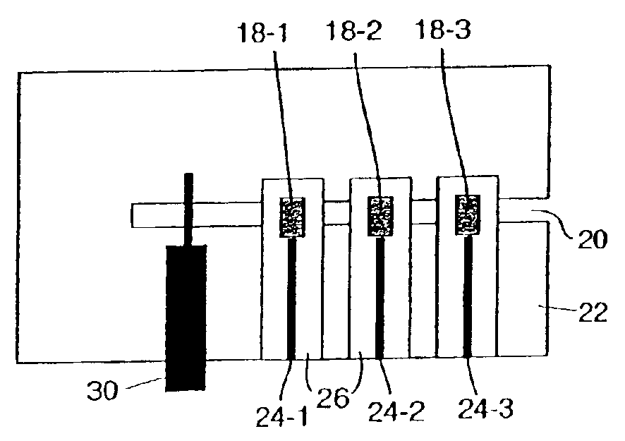
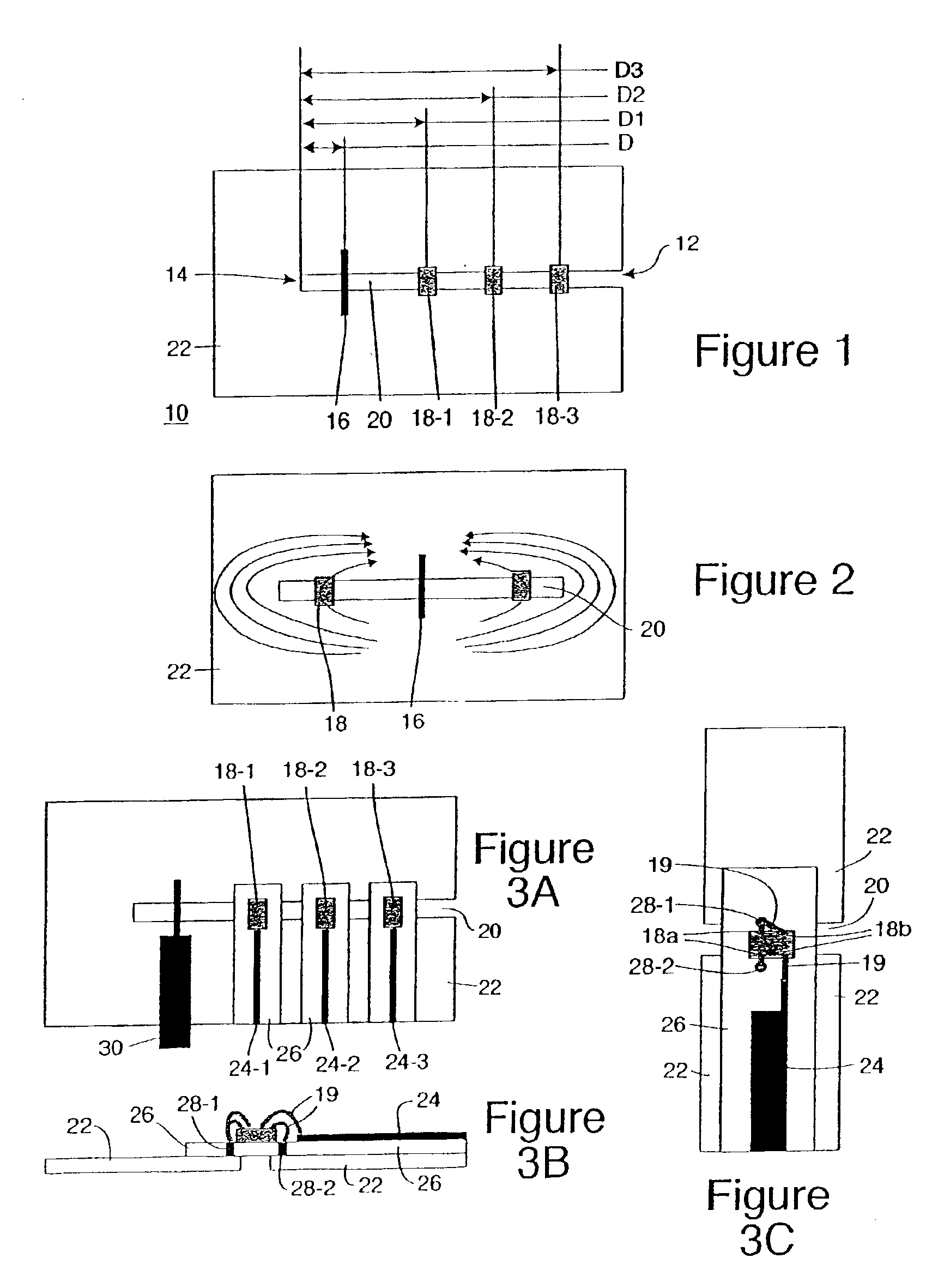
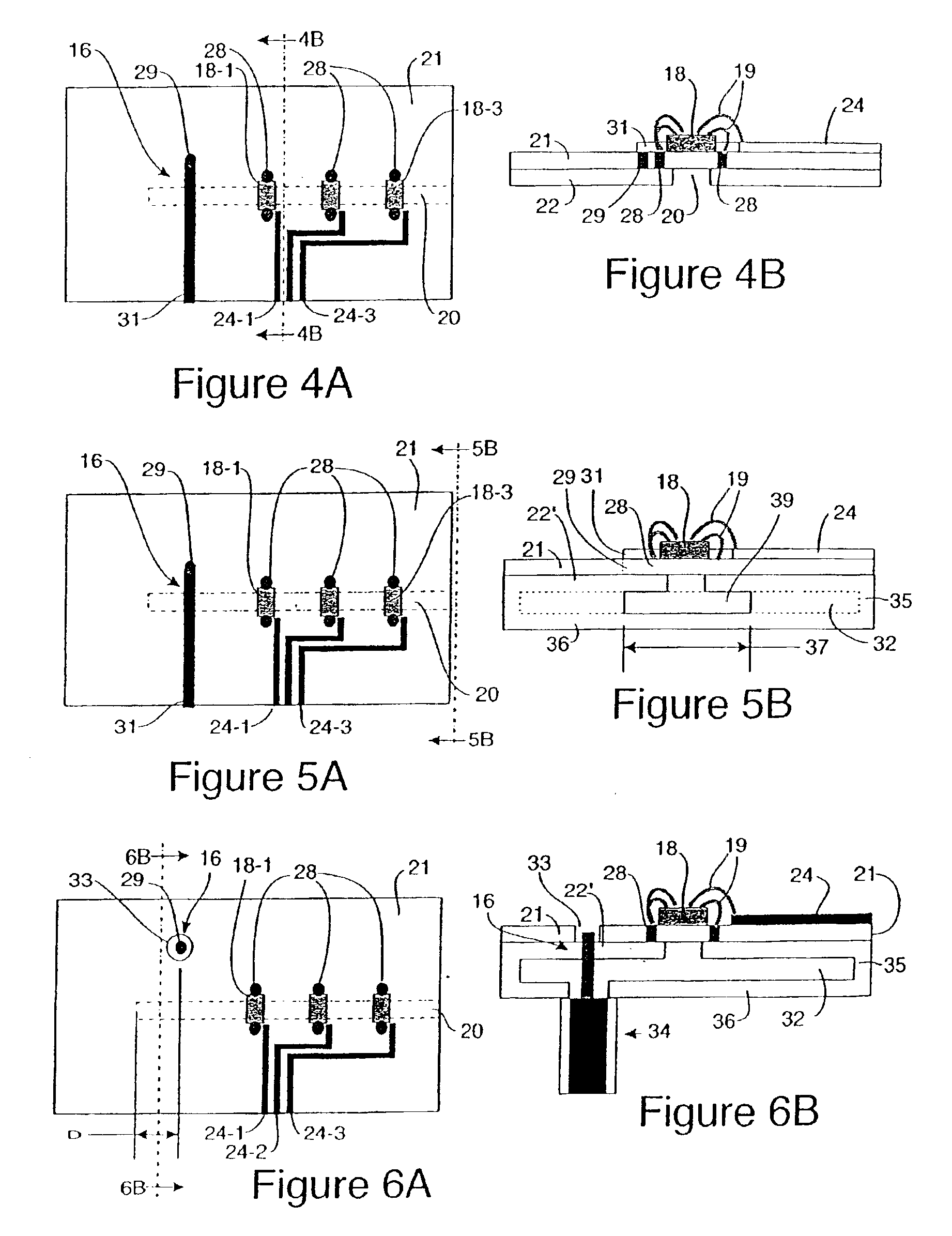
A MEMS tuned slot antenna has several applications in the areas of frequency-tunable antennas, diversity antennas, smart antennas, and phased arrays. In its most basic form (see FIG. 1), this invention consists of a slot antenna 10 which is open at one end 12 and closed at the other end 14. The antenna has a feed point 16 near the closed end 14 of the slot 20. The location of the feed point 16 depends on the antenna geometry, but is typically disposed a distance D much less than a wavelength, usually on the order of one-eighth to one-tenth wavelength, from the closed end 14 of the slot. Between the feed point 16 and the open end 12 of the slot are disposed a series of RF MEMS switches 18-1, 18-2, 18-3 . . . which can be opened or closed by voltages applied to control lines 24-1, 24-2, 24-3 . . . (see FIG. 3). The MEMS switches 18-1, 18-2, 18-3 bridge the slot 20. By opening and closing the MEMS switches 18-1, 18-2, 18-3 . . . , one can vary the effective length of the slot 20, and t...


PUM


Abstract

A slot antenna for receiving and/or transmitting a RF signal at a desired one of a plurality of different frequencies. The slot antenna includes at least one conductive sheet having a slot defined therein, the slot being longer than it is wide and having at least one end which is open. A plurality of switch members are mounted along said slot close to the open end thereof, each of said plurality of switch members acting, when closed, to couple the at least one conductive sheet on one side of said slot to the at least one conductive sheet on a second side thereof. A feed point is provided for adjacent said slot. The plurality of switch members are closable in a controlled manner to change a desired resonance frequency at which the slot antenna receives and/or transmits the RF signal.

Description

TECHNICAL FIELDThis invention relates to the field of tunable antennas using RF MEMS switches. It includes an open ended, (and possibly) cavity backed slot antenna, which has one or more RF MEMS switches to provide a variety of functions. Depending on the particular design of the antenna, the switches can be used to perform frequency tuning, to adjust the radiation pattern (as in switched-beam diversity), to adjust the polarization, or to adjust the phase of the radiated wave for phased array applications.BACKGROUND OF THE INVENTIONPrior art tunable antennas utilizing MEMS switches include tunable dipoles (which suffer from interference from the DC bias lines for the MEMS switches), ordinary slot antennas (which suffer from limited tunability due to the low-impedance current path around the outside of the slot), and patch antennas (which suffer from limited tunability due to the difficulty of detuning an extended resonant structure by a significant amount without significant design ...

Claims


Application Information

Patent Timeline
IPC IPC(8): H01Q5/00H01Q13/10H01Q3/24H01Q5/10H01Q21/30
CPCH01Q13/103H01Q9/14H01L24/45H01L2224/45144H01L2924/30107H01L2924/01013H01L2924/3025H01L2224/48091H01L2924/01079H01L2924/3011H01L2924/00014H01L2924/00H01L2924/12034
Inventor SIEVENPIPER, DANIEL F.
Owner HRL LAB
Why Eureka
Try Eureka