Multi-band antenna arrangement

a multi-band antenna and antenna technology, applied in the structural form of radiating elements, resonant antennas, antenna earthings, etc., can solve the problems of space saving in the positioning of antenna elements

Active Publication Date: 2007-04-17
NOKIA TECH OY
View PDF8 Cites 76 Cited by
  • Summary
  • Abstract
  • Description
  • Claims
  • Application Information

AI Technical Summary

Benefits of technology

[0010]According to one embodiment of the invention there is provided an antenna arrangement comprising: a ground plane; a ground point connected to the ground plane; a feed point; a λ / 2 antenna element connected to the ground point and to the feed point and extending between the ground point and the feed point as a loop that defines an area; and a λ / 4 antenna element located within the area. The relative positioning of the antenna elements saves space.

Problems solved by technology

The relative positioning of the antenna elements saves space.

Method used


Image

  • Multi-band antenna arrangement
  • Multi-band antenna arrangement
  • Multi-band antenna arrangement

Examples


Embodiment Construction

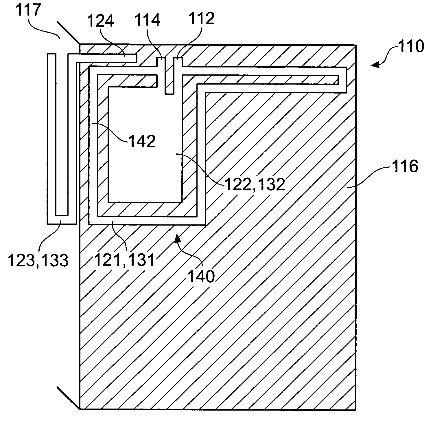
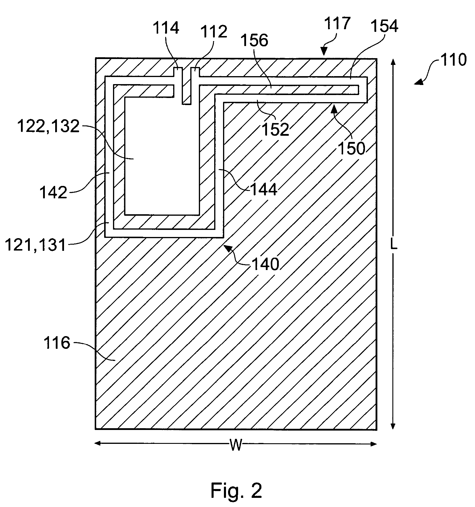
[0021]A RF antenna arrangement 110 that enables a radio communication device to communicate in the multiple bands is schematically illustrated in FIG. 2.

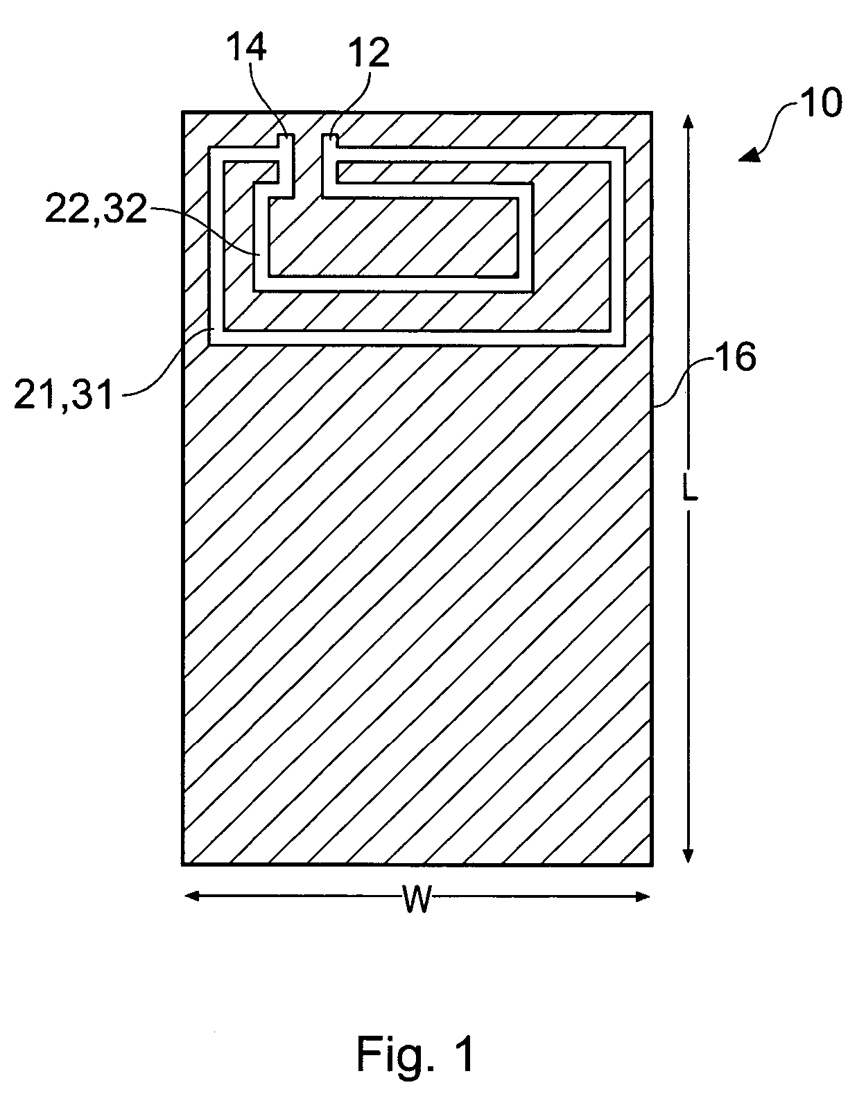
[0022]The antenna arrangement 110 comprises: a feed point 112; a ground (short-circuit) point 114 connected to a ground plane 116; a first planar antenna element 121 extends between the feed point 112 and the ground point 114 to form a balanced loop antenna 131 of electrical length L1; and a second planar antenna element 122 is connected to the feed point 112 and the ground point 114 to form an unbalanced λ / 4 antenna 132 of electrical length L2. The λ / 4 antenna 132 is a planar inverted F antenna (PIFA). In other embodiments, the λ / 4 antenna 32 may be a planar inverted L antenna (PILA) which is not directly connected to the feed point 112 but is instead indirectly fed via electromagnetic coupling provided by the loop antenna 131.

[0023]The first planar antenna element 121 is, for example, formed from a strip of metal foil and the seco...


PUM


Abstract

An antenna arrangement comprising: a ground plane; a ground point connected to the ground plane; a feed point; a λ / 2 antenna element connected to the ground point and to the feed point and extending between the ground point and the feed point as a loop that defines an area; and a λ / 4 antenna element located within the area.

Description

FIELD OF THE INVENTION[0001]Embodiments of the present invention relate to a multi-band antenna arrangement.BACKGROUND TO THE INVENTION[0002]Some radio communication devices communicate in more than one licensed frequency band. For example, a mobile cellular telephone may communicate more than one of the following bands US-GSM (824–894 MHz), E-GSM (880–960 MHz), PCN1800 (1710–1880 MHz), PCS1900 (1850–1990 MHz).[0003]One RF antenna arrangement 10 that enables a radio communication device to communicate in the multiple bands is illustrated in FIG. 1.[0004]The antenna arrangement 10 comprises: a feed point 12; a ground (short-circuit) point 14 connected to a ground plane 16; a first planar antenna element 21 extends between the feed point 12 and the ground point 14 to form a first loop antenna 31 of electrical length L1′; and a second planar antenna element 22 extends between the feed point 12 and the ground point 14 to form a second loop antenna 32 of electrical length L2′.[0005]The g...

Claims


Application Information

Patent Timeline
Patent Type & Authority Patents(United States)
IPC IPC(8): H01Q1/38
CPCH01Q1/243H01Q7/00H01Q5/40H01Q21/30H01Q5/371H01Q9/0421
Inventor WANG, HANYANGZHENG, MINGBRETT, SEAN
Owner NOKIA TECH OY
Why Eureka
Try Eureka