Method of making optical fiber with reduced E-band and L-band loss peaks

a technology of optical fiber and loss peak, which is applied in the field of optical fibers, can solve the problems of loss peak, transmission channel dropout in amplified dwdm transmission system,

Inactive Publication Date: 2005-03-08
FURAKAWA ELECTRIC NORTH AMERICA INC
View PDF8 Cites 2 Cited by
  • Summary
  • Abstract
  • Description
  • Claims
  • Application Information

AI Technical Summary

Benefits of technology

Applicants have further discovered that these loss peaks are due to carbon contamination of the transmission fiber. Thus optical fibers should be fabricated essentially free of carbon contamination. This means eliminating carbon-containing reagents in preform and tube-making processes.

Problems solved by technology

Because the peaks are relatively narrow, they cannot be easily removed by conventional gain equalizers in long haul transmission systems, and although the peaks are relatively small, they can nonetheless cause transmission channels to drop out in amplified DWDM transmission systems.
Applicants have further discovered that these loss peaks are due to carbon contamination of the transmission fiber.

Method used


Image

  • Method of making optical fiber with reduced E-band and L-band loss peaks
  • Method of making optical fiber with reduced E-band and L-band loss peaks
  • Method of making optical fiber with reduced E-band and L-band loss peaks

Examples


example

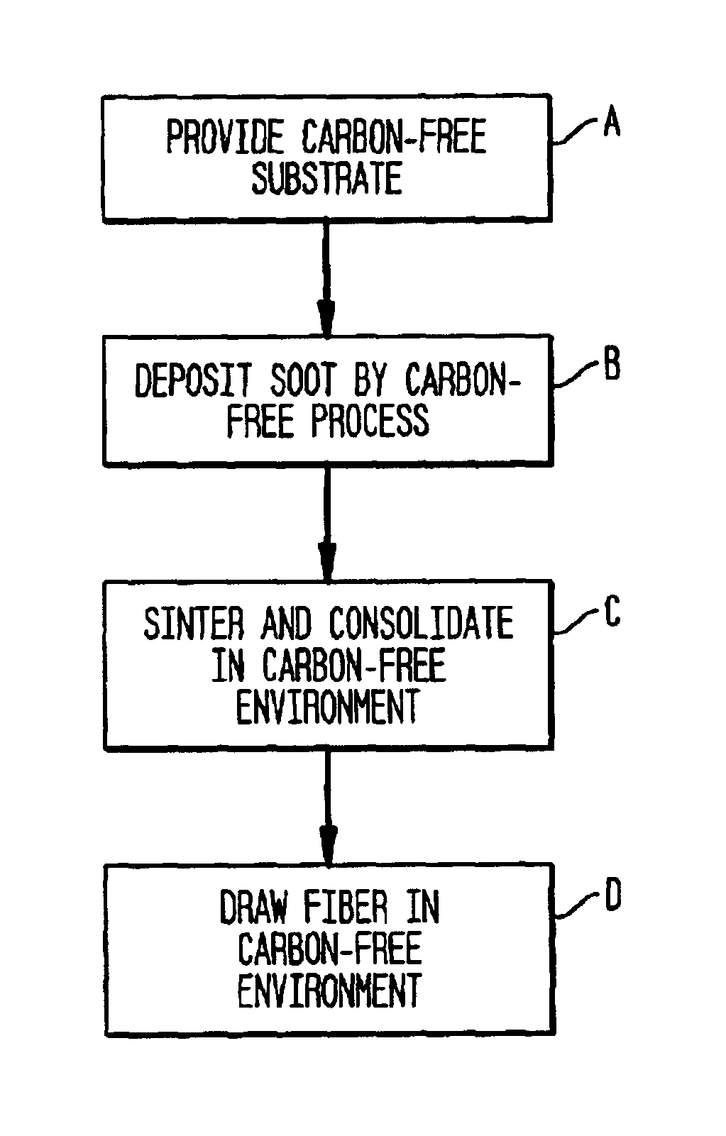
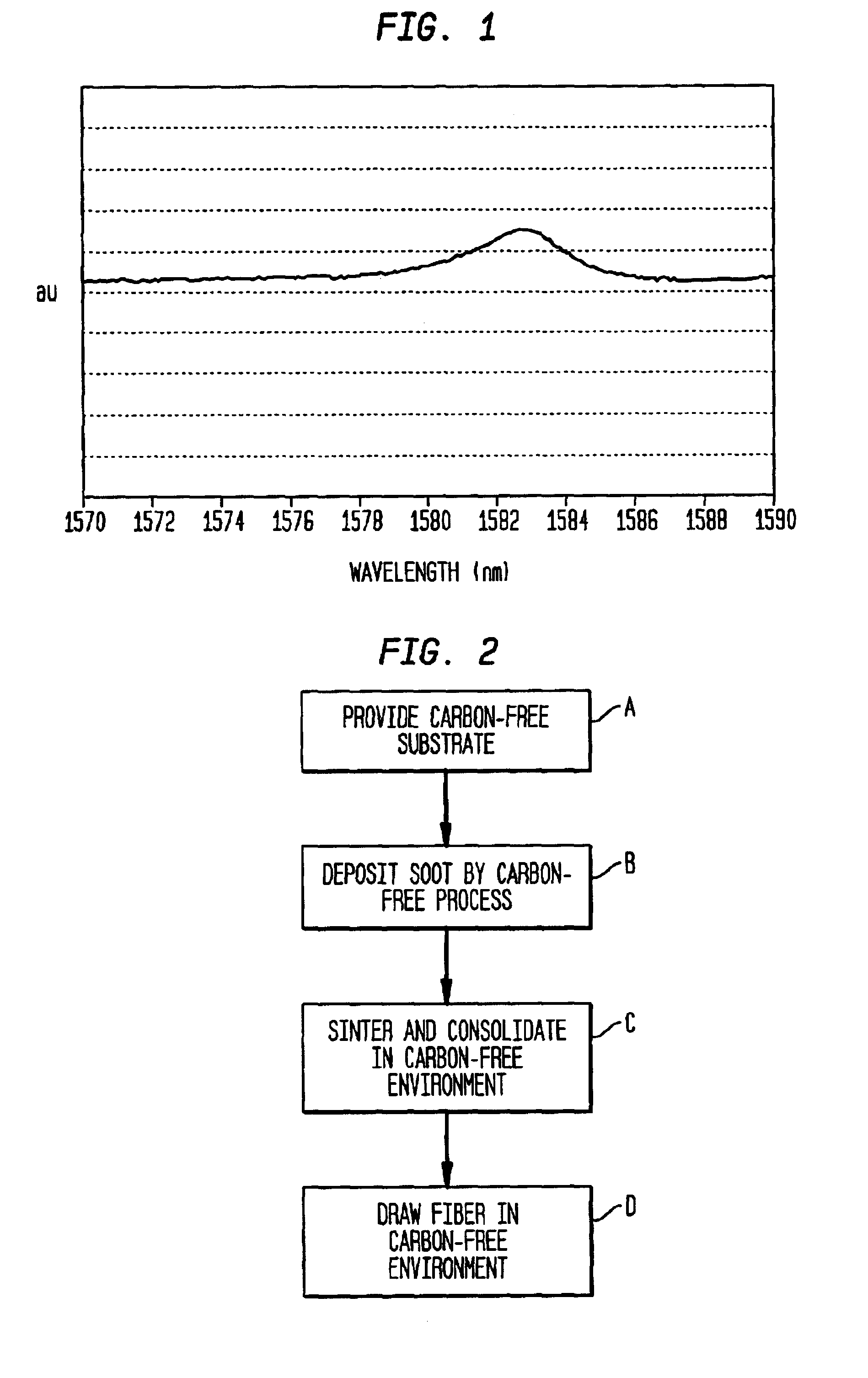
A carbon-free starting tube comprising carbon-free silica is obtained from Heraeus Tenevo under the tradename F300. The tube is made by OVD without using carbon-containing reagents. It has dimensions 21.58 mm in ID and 28.0 mm in OD.

Glass soot is deposited on the interior surface of the starting tube by the MCVD process modified to be essentially free of carbon-containing reagents. In a specific case, the following conditions are used to deposit glass on the starting tube:

Carrier O2Carrier O2Excessfor SiCl4for GeCl4SF6O2HeCl2TempRegion(slpm)(slpm)(sccm)(slpm)(slpm)(sccm)Δ(C.)Core0.460.4902.04.000.3%2050Trench1.28022.02.03.20−0.1%2037-2100Collapse0000075.02100

The deposited soot is sintered and consolidated in a Cl2 environment essentially free of carbon-containing reagents, and the structure is collapsed into a solid preform rod. After collapse, carbon-free fiber is drawn from the preform in a carbon-free refractory furnace. The drawn fiber is coated with a conventional urethane meth...


PUM

PropertyMeasurementUnit
wavelengthsaaaaaaaaaa

Abstract

Applicants have discovered the existence of loss peaks in optical fiber transmission systems using wavelengths in the E-band and the L-band. Specifically, they have discovered the existence of narrow loss peaks at 1440 nm, 1583 nm and 1614 nm. Because the peaks are relatively narrow, they cannot be easily removed by conventional gain equalizers in long haul transmission systems, and although the peaks are relatively small, they can nonetheless cause transmission channels to drop out in amplified DWDM transmission systems. Applicants have further discovered that these loss peaks are due to carbon contamination of the transmission fiber. Thus optical fibers should be fabricated essentially free of carbon contamination. This means eliminating carbon-containing reagents in preform and tube-making processes.

Description

FIELD OF THE INVENTIONThis invention relates to optical fibers and, in particular, to a method of making optical fibers having reduced E-band and L-band loss peaks and to fibers made by the method. The method and fibers are particularly useful for broadband transmission.BACKGROUND OF THE INVENTIONOptical fibers are key components in modern telecommunications systems. Basically, an optical fiber is a thin strand of glass capable of transmitting optical signals containing a large amount of information over long distance with low loss. Advantageously the fiber transmits all wavelengths of interest with the same low loss.In its simplest form, an optical fiber is a small diameter waveguide comprising a core having a first index of refraction peripherally surrounded by a cladding having a second (lower) index of refraction. Typically optical fibers are composed of high purity silica with minor concentrations of dopants to control the index of refraction.Optical fibers are typically fabric...

Claims


Application Information

Patent Timeline
Patent Type & Authority Patents(United States)
IPC IPC(8): C03C13/04C03C13/00C03B37/014G02B6/02
CPCC03B37/014C03C13/045C03B2201/03G02B6/02C03B2201/07
Inventor ATKINS, ROBERT M.LIU, ALICE W.KRISTENSEN, POULPEDERSEN, MORTEN .O SLASHED.STERGAARDKNUDSEN, STIG NISSENNIELSEN, JAN LEVINBROMAGE, JAKECHANG, KAI H.
Owner FURAKAWA ELECTRIC NORTH AMERICA INC
Why Eureka
Try Eureka