Non-linear axisymmetric potential flow boundary model for partially cavitating high speed bodies

a potential flow boundary model and non-linear axisymmetric technology, applied in the field of hydrodynamic flow computer models, can solve the problems of partial cavitation, unsteady phenomenon of partial cavitation, and inability to account for the transition cas

Inactive Publication Date: 2005-03-08
THE UNITED STATES OF AMERICA AS REPRESENTED BY THE SECRETARY OF THE NAVY
View PDF2 Cites 8 Cited by
  • Summary
  • Abstract
  • Description
  • Claims
  • Application Information

AI Technical Summary

Benefits of technology

Accordingly, the present invention provides a method for calculating cavity shape for partial cavities about an axisymmetric body having a cavitator located at the foremost end. The method includes receiving system parameter data including geometric data describing the axisymmetric body, a cavity length, and a convergence tolerance. Boundary element panels are distributed along the body-cavity surface and matrices are initialized for each boundary element panel using the unit dipole, unit source functions and known boundary values. Disturbance potential matrices are formulated for each boundary element panel using disturbance potentials, normal derivatives of disturbance potentials, and no net flux boundary conditions. The initialized matrices and the formulated

Problems solved by technology

High speed underwater vehicles, however, cause cavitation of the surrounding fluid.
Partial cavitation is an unsteady phenomenon that occurs when part of the supercavitating vehicle is traveling in the cavity.
These models, however, do not

Method used


Image

  • Non-linear axisymmetric potential flow boundary model for partially cavitating high speed bodies
  • Non-linear axisymmetric potential flow boundary model for partially cavitating high speed bodies
  • Non-linear axisymmetric potential flow boundary model for partially cavitating high speed bodies

Examples


Embodiment Construction

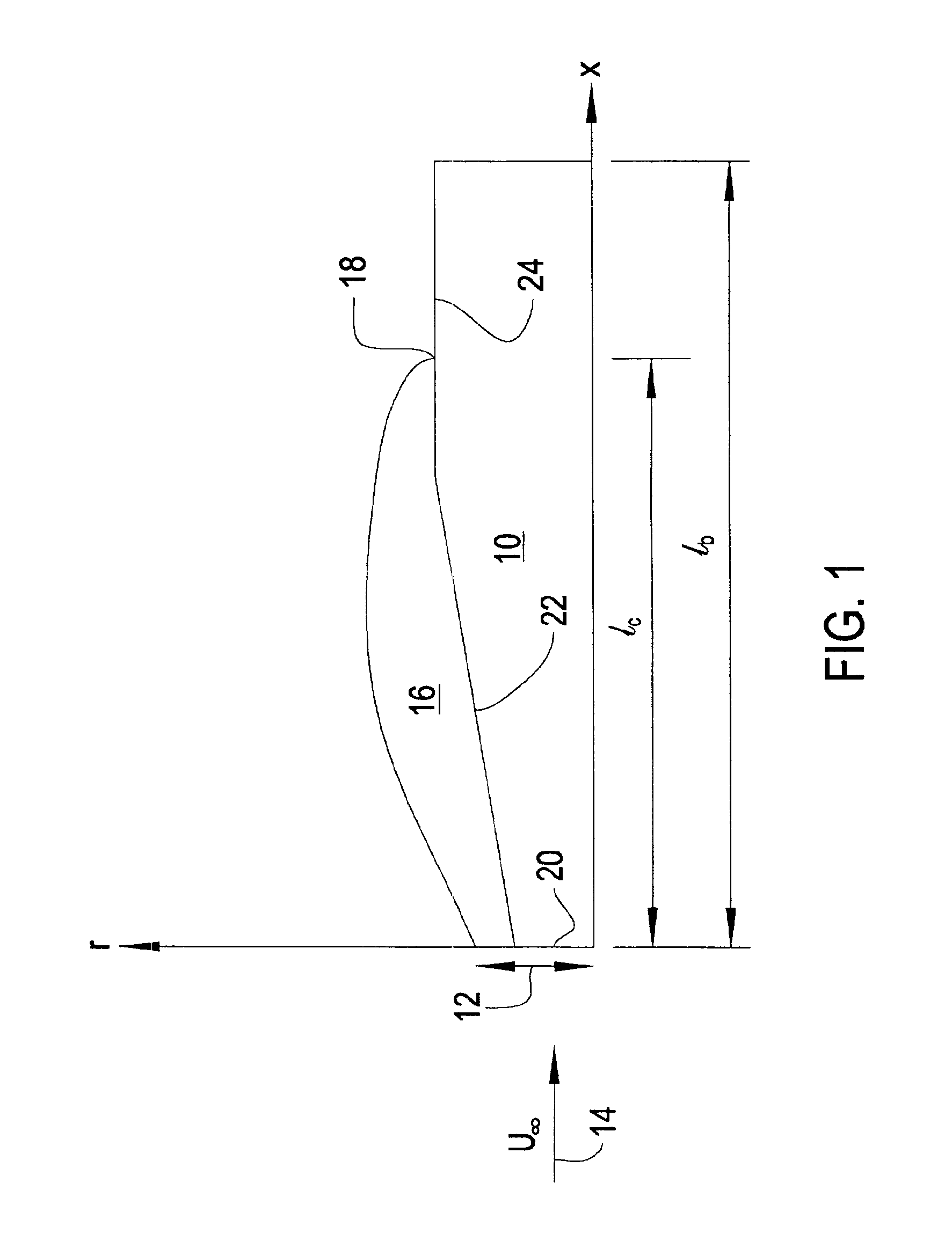
FIG. 1 shows a diagram of the physical problem of partial cavitation. FIG. 1 shows a radial cross section of an axisymmetric body 10. Axis r represents the radius from the axis of body 10. Axis x represents the length along the body 10 measured from a cavitator disk 12. Although a cavitator disk is shown, the model can calculate cavities for cavitator cones as well as cavitator disks. Flow, U∞, is in the direction of arrow 14. A cavity 16 is shown extending from the edge of the cavitator along the length of body 10. The length of the cavity, lc, is shown by dimension arrows. Likewise, the length of the body, lb, is also shown by dimension arrows.

Body 10 extends beyond a cavity closure 18. Cavity 16 is closed to the body 10 with a modified Riabouchinsky cavity termination wall. Cavity closure 18 can be positioned in either body conical section 22 or body cylindrical section 24. The plane of cavity closure 18 is referenced in the following disclosure as an endplate.

Body 10 has a flat ...


PUM


Abstract

A method for calculating parameters about an axisymmetric body in a cavity is provided. The user provides data describing the body, a cavity estimate, and convergence tolerances. Boundary element panels are distributed along the body and the estimated cavity. Matrices are initialized for each panel using disturbance potentials and boundary values. Disturbance potential matrices are formulated for each panel using disturbance potential equations and boundary conditions. The initialized matrices and the formulated matrices are solved for each boundary panel to obtain panel sources, dipoles and cavitation numbers. Forces and velocities are computed giving velocity and drag components. The cavity shape is updated by moving each panel in accordance with the calculated values. The method then tests for convergence against a tolerance, and iterates until convergence is achieved. Upon completion, parameters of interest and the cavity shape are provided. This invention also allows determiniation of cavity shape for a cavitation number.

Description

STATEMENT OF GOVERNMENT INTERESTThe invention described herein may be manufactured and used by or for the Government of the United States of America for governmental purposes without the payment of any royalties thereon or therefore.CROSS-REFERENCE TO RELATED PATENT APPLICATIONSNot applicable.BACKGROUND OF THE INVENTION(1) Field of the InventionThe present invention relates to computer model of hydrodynamic flows and more particularly, relates to modeling partially cavitating flows over a supercavitating axisymmetric body.(2) Description of the Prior ArtModeling of boundary flows about objects subject to laminar and turbulent flows is well known in the art. High speed underwater vehicles, however, cause cavitation of the surrounding fluid. Cavitation reduces pressure in the fluid below its vapor pressure causing the fluid to vaporize, allowing the undersea vehicle to travel with lower friction when the vehicle is completely surrounded by the cavity.Partial cavitation is an unsteady ...

Claims


Application Information

Patent Timeline
IPC IPC(8): B63B9/00F15D1/10F15D1/00
CPCF15D1/10B63B9/002B63B71/10
Inventor VARGHESE, ABRAHAM N.UHLMAN, JAMES S.
Owner THE UNITED STATES OF AMERICA AS REPRESENTED BY THE SECRETARY OF THE NAVY
Why Eureka
Try Eureka