Data structure for write pending

Inactive Publication Date: 2005-03-08
EMC IP HLDG CO LLC
View PDF6 Cites 26 Cited by
  • Summary
  • Abstract
  • Description
  • Claims
  • Application Information

AI Technical Summary

Benefits of technology

One or more aspects of the invention may include one or more of the following advantages. Unlike prior write tree data structures, which are geared towards finding a write pending which is physically closest to the current head location and requires multiple memory accesses, the write pending list and destaging control mechani

Problems solved by technology

Since reading and writing to disks is still a relatively slow operation, many data storage systems use a cache memory to speed up the transfer of information to/from the disks.
As the number of logical volumes on a disk grows, however, the technique becomes much less efficient with respect to seek minimization.
Moreover, because searching the write tre

Method used


Image

  • Data structure for write pending
  • Data structure for write pending
  • Data structure for write pending

Examples


Embodiment Construction

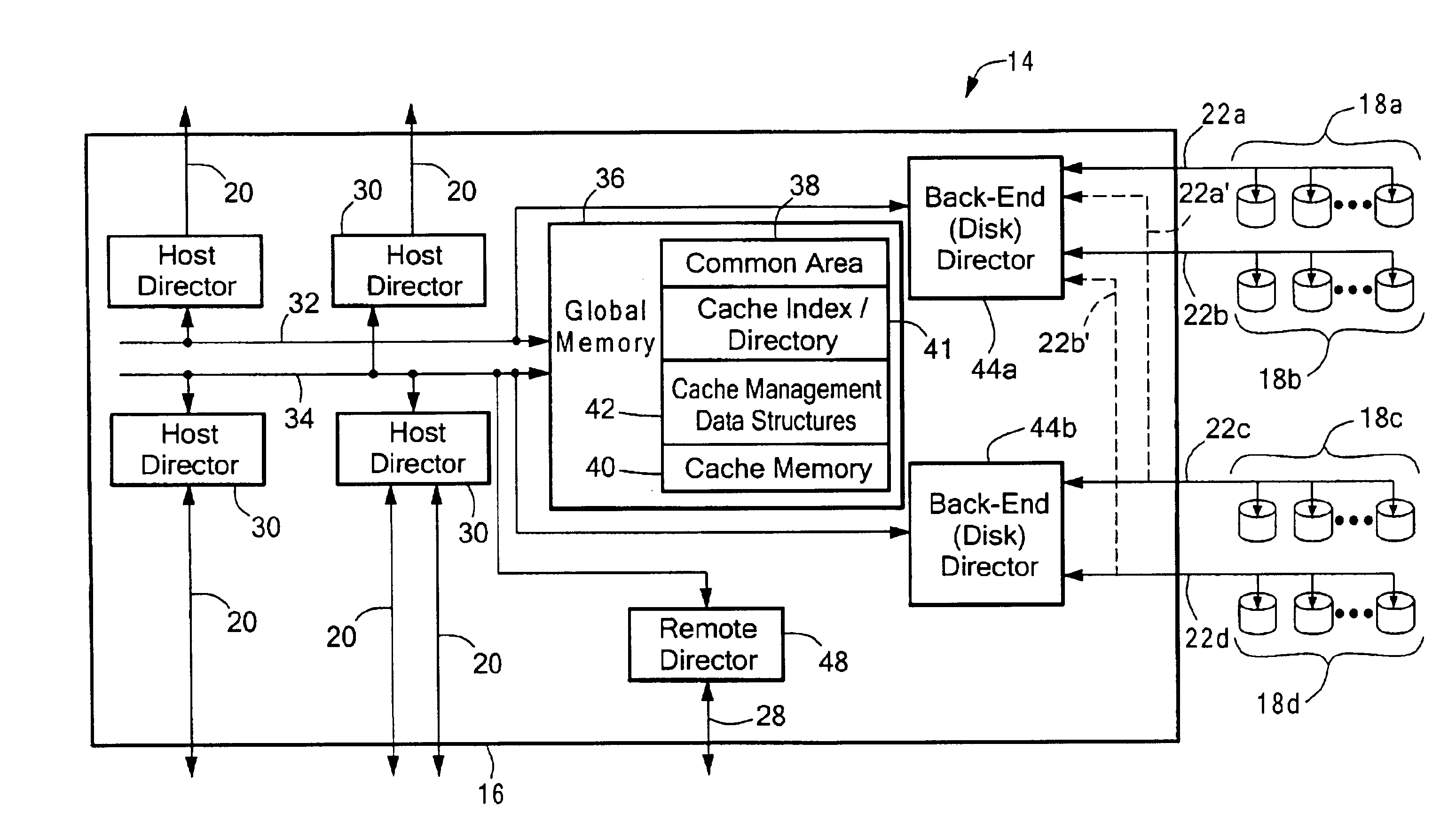
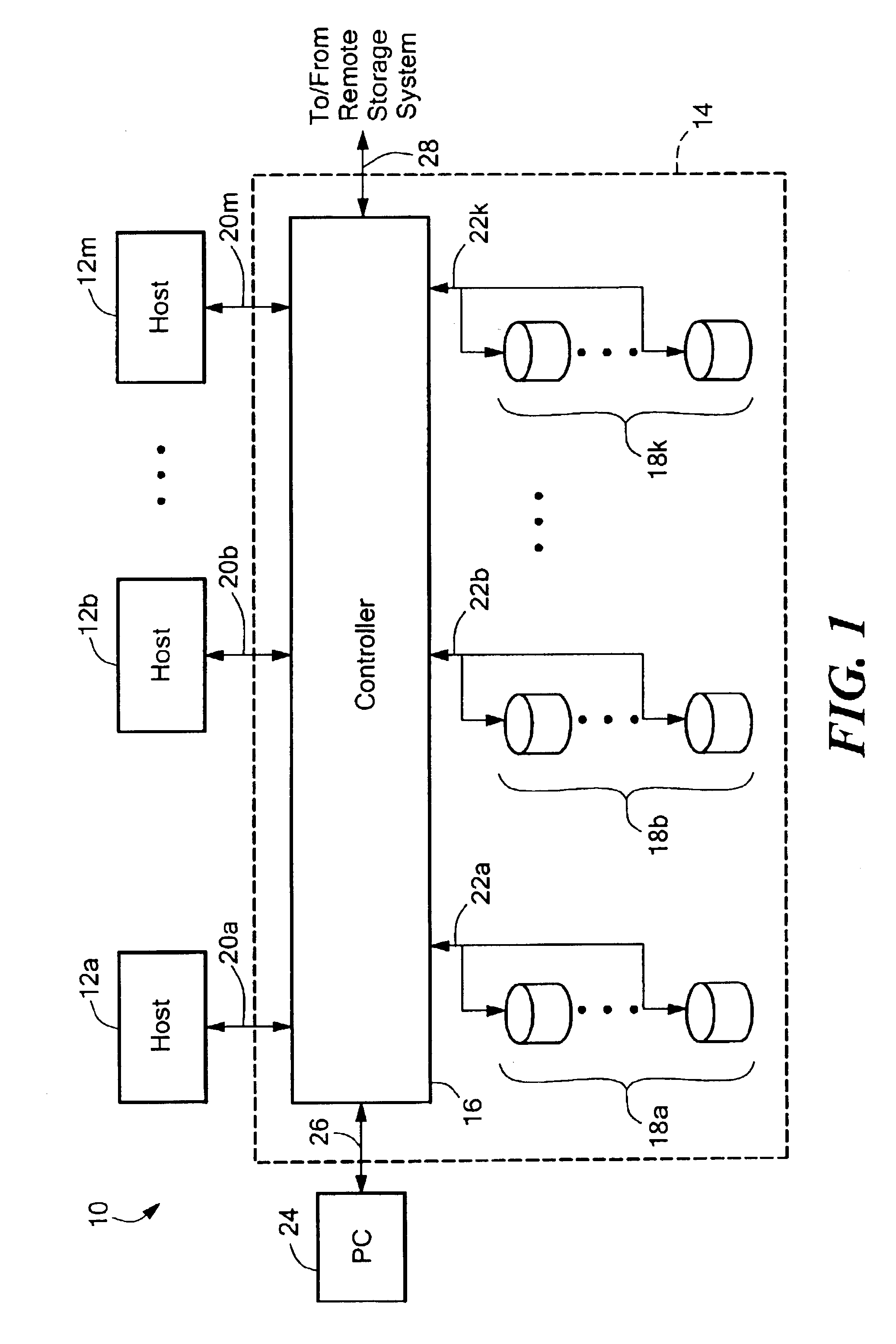
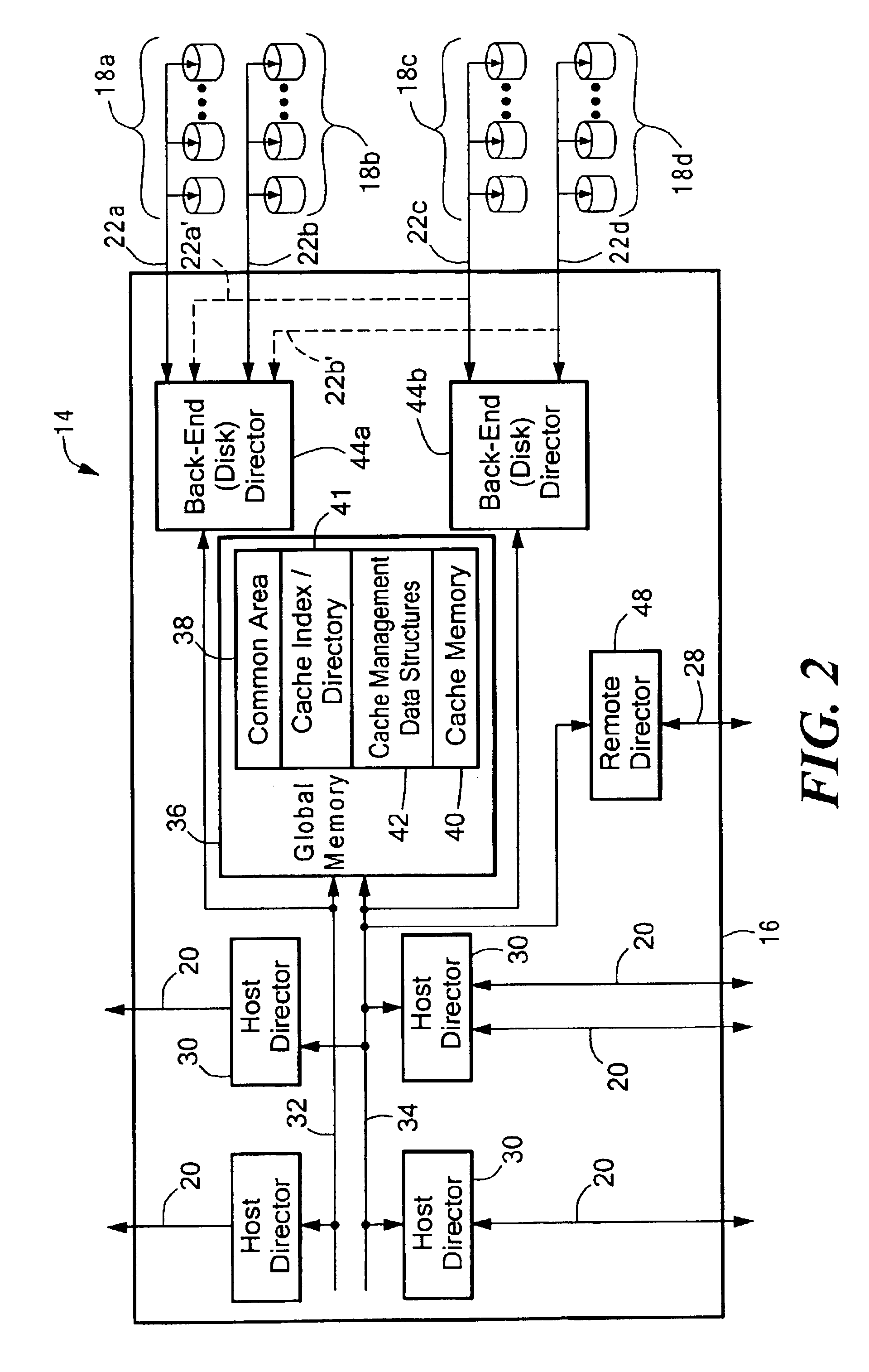
Referring to FIG. 1, a data processing system 10 includes host computers 12a, 12b, . . . , 12m, connected to a data storage system 14. The data storage system 14 receives data and commands from, and delivers data and responses to, the host computers 12. The data storage system 14 is a mass storage system having a controller 16 coupled to pluralities of physical storage devices shown as disk devices 18a, disk devices 18b, . . . , disk devices 18k. Each of the disk devices 18 is logically divided, in accordance with known techniques, into one or more logical volumes. The logical volumes can be mirrored on one or more other disk devices.

The controller 16 interconnects the host computers 12 and the disk devices 18. The controller 16 can be, for example, the controller of the Symmetrix data storage system from EMC Corporation. Although described herein as a component of a data storage system, the controller 16 could also be a separate appliance or server. The controller 16 thus receives ...


PUM


Abstract

Destaging activities in a data storage system are controlled by providing a write pending list of elements, where each element is defined to store information related to a cache memory data element for which a write to storage is pending, and maintaining the write pending list so that destaging of a data element can be based on the maturity of the pending write.

Description

BACKGROUNDThe invention relates generally to destaging operations in data storage systems.Mass storage systems typically employ a large number of storage devices, such as disk drives, that are accessible by one or more host processors or computers. Since reading and writing to disks is still a relatively slow operation, many data storage systems use a cache memory to speed up the transfer of information to / from the disks. In such systems, the host computers interact with the cache memory on all transfers to and from storage devices.For example, if data is modified by a host computer, the modified data is written to cache memory, and later written back to disk (the latter operation often being referred to “destaging”). When the data storage system employs mirroring, the data to be destaged must be written to each mirror, however not necessarily at the same time.Typically, a data structure is maintained to indicate which data elements in cache memory have been modified and therefore n...

Claims


Application Information

Patent Timeline
IPC IPC(8): G06F12/00G06F12/08
CPCG06F12/0804
Inventor NAAMAD, AMNONYOCHAI, YECHIELMORE, SACHIN
Owner EMC IP HLDG CO LLC
Why Eureka
Try Eureka