Firing flap dispenser

a dispenser and flap technology, applied in the field of dispensers, can solve problems such as the dispenser is susceptible to some improvemen

Inactive Publication Date: 2005-03-15
CLINICAL DESIGNS
View PDF15 Cites 54 Cited by
  • Summary
  • Abstract
  • Description
  • Claims
  • Application Information

AI Technical Summary

Benefits of technology

The object of the present invention is to provide improved breath actuated, k...

Problems solved by technology

Nevertheless, I feel that the disp...

Method used


Image

  • Firing flap dispenser
  • Firing flap dispenser
  • Firing flap dispenser

Examples


Embodiment Construction

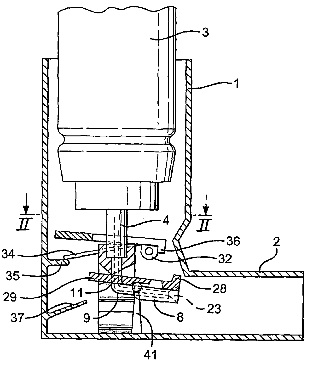
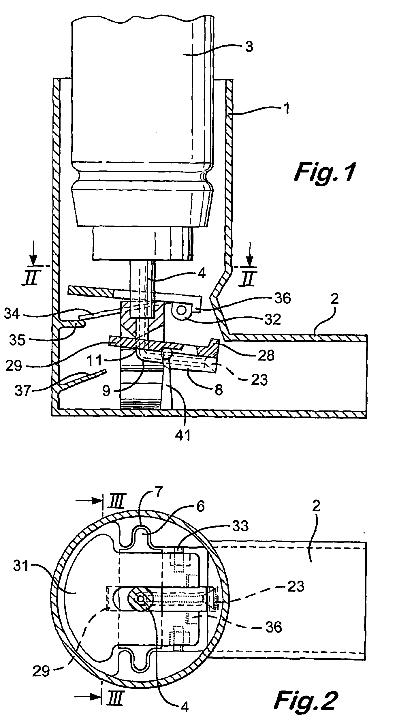
Referring to the drawings, the breath actuated dispenser there-shown has a generally L-shaped hollow body 1 with a mouthpiece 2. An aerosol drug can 3 is mounted in the body with good clearance to allow breathing through the body when the can is installed. The can has a dispensing spout 4, which engages a receptor moulding 5, the receptor moulding being engaged in the body via lugs 6 in slots 7 and incorporating a movable outlet member 8 and a kink valve 9. The parts (other than the can) are of injection moulded plastics material.

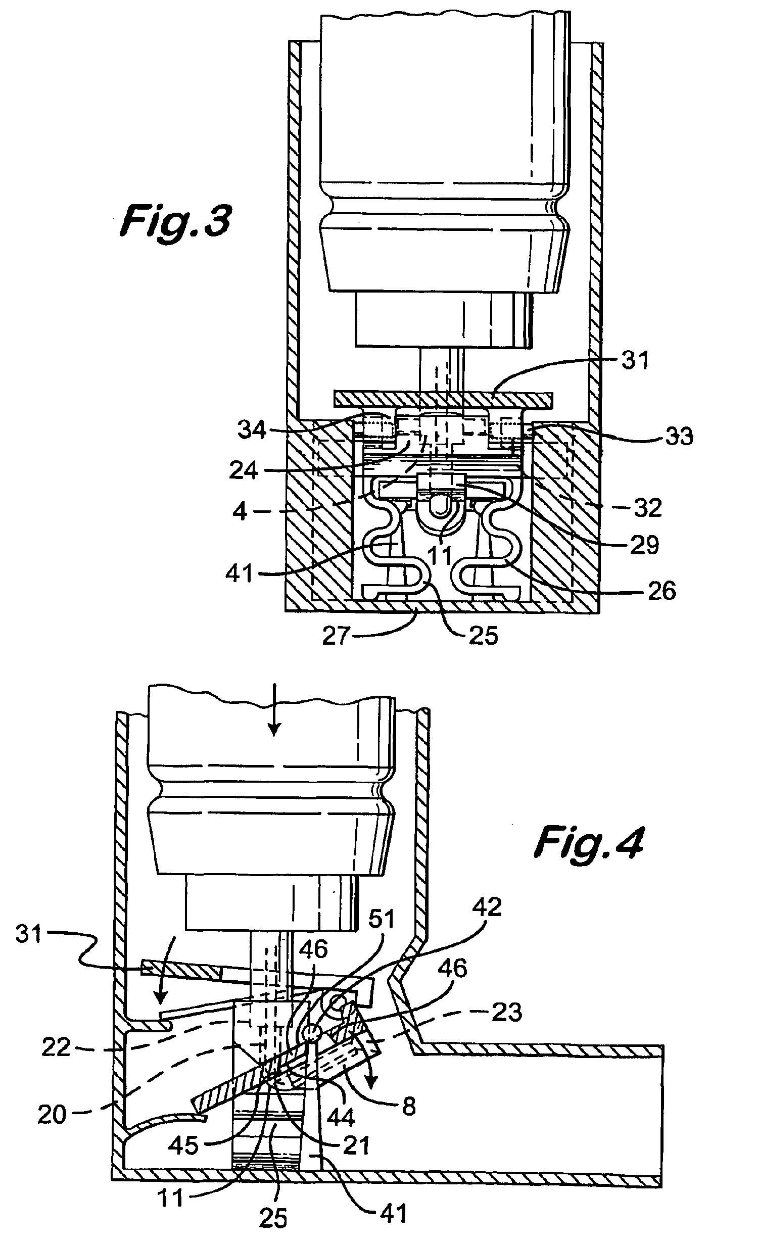
The outlet member 8 is connected to the main receptor moulding part by a living hinge 11. The receptor is moulded with the outlet member angled down with respect to the use orientation and a linear passage 20 through it. The central portion 21 of the passage has a thin wall thickness, whereby when the flap is hinged up, the passage kinks and closes. The upper end 22 of the passage is of larger diameter to receive the spout of the can. The lower end of the p...


PUM


Abstract

A breath actuated dispenser there-shown has a generally L-shaped hollow body 1 with a mouthpiece 2. An aerosol drug can 3 is mounted in the body. The can has a dispensing spout 4, which engages a receptor moulding 5 incorporating a living hinge 11, a movable outlet member 8 and a kink valve 9. A flap member 31 is pivotally mounted between the can and the receptor moulding. Breathing in through the dispenser by the patient will cause the flap to be drawn down against its spring 34. The outlet member is then tipped down by the spring 37 to point out of the mouthpiece 2, whence the dose is dispensed by opening of the kink valve.

Description

TECHNICAL FIELDThe present invention relates to a dispenser, particularly though not exclusively for dispensing aerosol or powder borne medicaments.BACKGROUND OF THE INVENTIONIn my prior International Patent Application, PCT / GB98 / 00770, at least as amended on entry in the European Regional Phase, there is described and claimed:A dispenser for a gaseous, gas borne or droplet substance, the dispenser including:a body having a mouthpiece with an inhalation / insufflation orifice at its end;a junction in the body for a source of gas or evaporable liquid comprising or containing the said substance (the source being carried by the body); anda breath actuable valve, for controlling the release of said gas or liquid, comprising:a valve inlet connected to the junction;a valve outlet;a flexible tube extending from the junction, between the inlet and the outlet, for receiving the said gas or liquid, the tube having a portion which is movable between a closed position in which the tube is kinked ...

Claims


Application Information

Patent Timeline
IPC IPC(8): A61M15/00F16K7/00F16K7/06
CPCF16K7/068A61M15/0091A61M15/009A61M15/0093
Inventor BACON, RAYMOND JOHN
Owner CLINICAL DESIGNS
Why Eureka
Try Eureka