
Tensioning device for cable inserted through flexible tube

Inactive Publication Date: 2005-03-15
MITSUI KINZOKU ACT
View PDF11 Cites 26 Cited by
  • Summary
  • Abstract
  • Description
  • Claims
  • Application Information

AI Technical Summary

Benefits of technology

An object of the present invention is to provide a tensioning device which effectuates the simple connection of a cable to a movable member such as a sliding door.

Problems solved by technology

However, since the above tensioning device is not capable of temporarily removing the tension of the cable, the cable must be forcibly pulled out of the end of the flexible tube against the force of the coil spring, when connecting the end of the cable to the sliding door.

Method used


Image

  • Tensioning device for cable inserted through flexible tube
  • Tensioning device for cable inserted through flexible tube
  • Tensioning device for cable inserted through flexible tube

Examples


Embodiment Construction

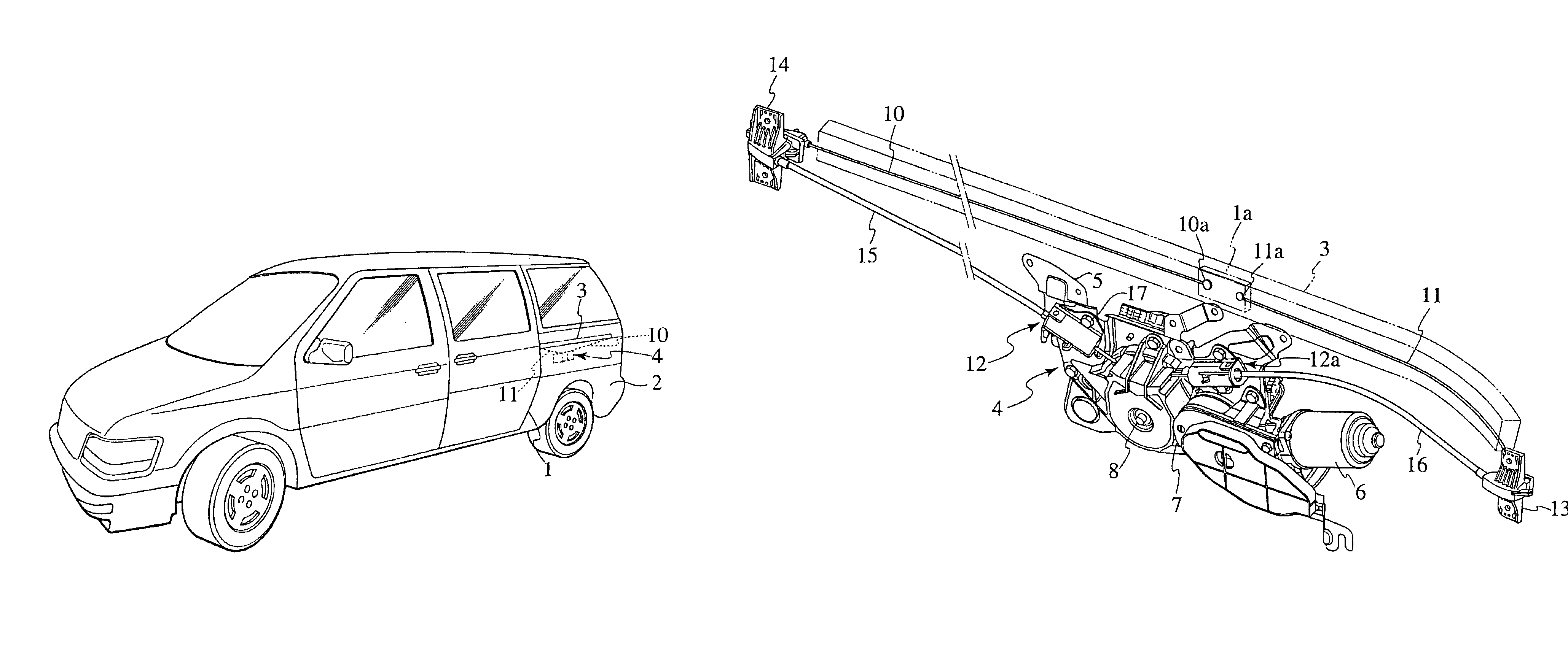
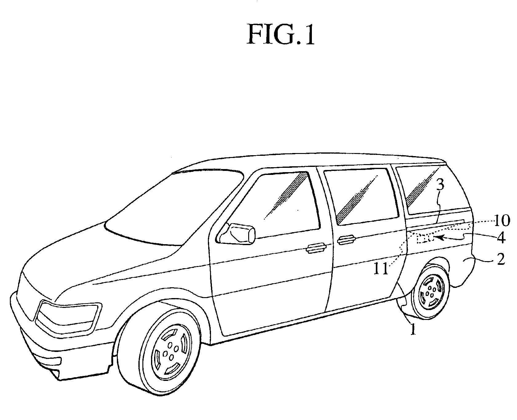
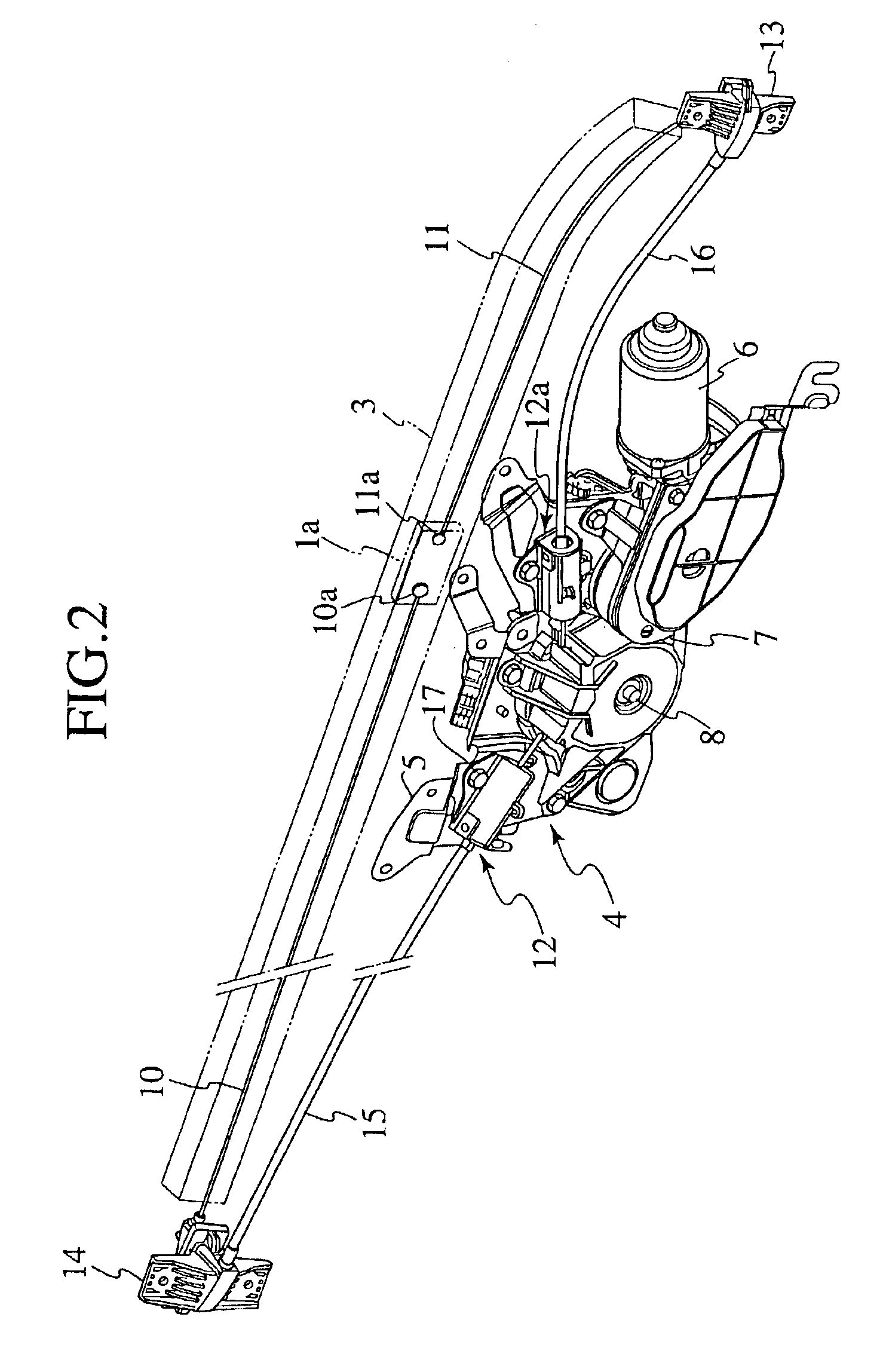
An embodiment of the present invention adopted in a power sliding door system will be explained below with reference to the drawings. Note that, in FIGS. 2 and 3, “front” and “rear” of the vehicle of FIG. 1 are on right and left sides, respectively.

In the power sliding door system, a sliding door 1 as a movable member is supported, as shown in FIG. 1, on a vehicle body panel 2 so as to be slidable in a vehicle longitudinal direction.

The sliding door 1 is guided by longitudinally extending upper and lower guide rails (not shown) provided on upper and lower peripheral edges around a door opening on the body panel 2, respectively, and a longitudinally extending center guide rail 3 fixed on rear side of the body panel 2. The sliding door 1 travels along the guide rails between a closed position at the front end of the travel, where the sliding door closes the door opening, and an open position at the rear end of the travel, where the door opening is fully opened (not shown). Moreover, t...


PUM


Abstract

A tensioning device for a cable inserted through a flexible tube, in which the flexible tube is fixed at one end to a stationary member, and the cable is connected to a movable member relative to the stationary member. The tensioning device includes a socket fixed to the stationary member, a plug provided on the other end of the flexible tube, a resilient member and locking means. The socket has a space therein. In the space, the plug supports the flexible tube so as to be movable in an axial direction of the cable, and the resilient member presses the plug toward the end of the space of the socket. The locking means fastens the plug in a position where the resilient member is compressed.

Description

BACKGROUND OF THE INVENTION1. Field of the InventionThe present invention relates to a tensioning device for a cable inserted through a flexible tube, in which the cable is connected to a movable member provided on a stationary member.2. Description of the Related ArtSome modern vehicles employ a power sliding door system in which a sliding door is automatically opened and closed by traveling along a guide rail provided on a vehicle side body.The actuator assembly of the system includes a cable connected to the sliding door and a motor-operated drum for winding and unwinding the cable. The cable is extended from the drum through a flexible tube to the end of the guide rail, out of the flexible tube, along the guide rail, and connected to the sliding door at its end. By rotating the drum for winding or unwinding the cable thereon, the sliding door travels along the guide rail, thus allowing it to be opened or closed.Between the end of the flexible tube and a stationary member fixed t...

Claims


Application Information

Patent Timeline
IPC IPC(8): E05F15/14E05F11/04B60J5/06
CPCE05F15/646E05Y2900/531
Inventor KITA, SHINICHIRO
Owner MITSUI KINZOKU ACT
Learn More