Battery Module

a battery module and module technology, applied in battery/fuel cell control arrangement, process and machine control, instruments, etc., can solve the problems of large number of cables or wires, labor-intensive and cost-intensive cable or wire harness routing, and the overcharging of individual energy stores can occur, so as to reduce the overall weight or the overall mass of the arrangement can be enormously reduced, and the cable routing is extremely simple.

Active Publication Date: 2013-05-09
INFINEON TECH AUSTRIA AG
View PDF7 Cites 7 Cited by
  • Summary
  • Abstract
  • Description
  • Claims
  • Application Information

AI Technical Summary

Benefits of technology

[0021]It is particularly advantageous that the cable routing is extremely simple and that the battery modules are connected to each other by simple cable connections. Two adjacent battery modules only require two connection cables the length of which corresponds to the distance between the battery modules. Alternatively, the battery modules can also be plugged into each other or can be clamped together. This results in the advantage that, due to the low number of used cables or wires, cable or wire harnesses can be omitted and the overall weight or the overall mass of the arrangement can be enormously reduced, and that the costs can be drastically reduced due to the reduced material requirements.
[0022]Particularly advantageously it can be provided that the first connection lying at the end of the series connection and the first compensation connection lying at the end of the series connection are connected with each other, possibly via an electrically conductive first connection element, and that the second connection lying at the end of the series connection and the second compensation connection lying at the end of the series connection are connected with each other, possibly via an electrically conductive second connection element. This enables a particularly effective returning of the energy discharged by the energy stores to the entirety of the battery modules connected in series.

Problems solved by technology

In the course of the charging process the problem exists that the individual energy stores are charged differently due to the different ageing properties, and that an undesirable overcharging of individual energy stores can occur until the required charging voltage of the arrangement as a whole is reached.
It is disadvantageous in prior art that for the energy discharge from the individual energy stores there are required two lines to a respective one of the two ends of the battery modules connected in series, respectively.
There is required a large number of cables or wires as well as a large amount of work for their connection.
In particular in the automotive sector, the routing of cable or wire harnesses is labor-intensive and cost-intensive.
In mass production, the use of a plurality of cables is costly.

Method used


Image

  • Battery Module
  • Battery Module
  • Battery Module

Examples


Embodiment Construction

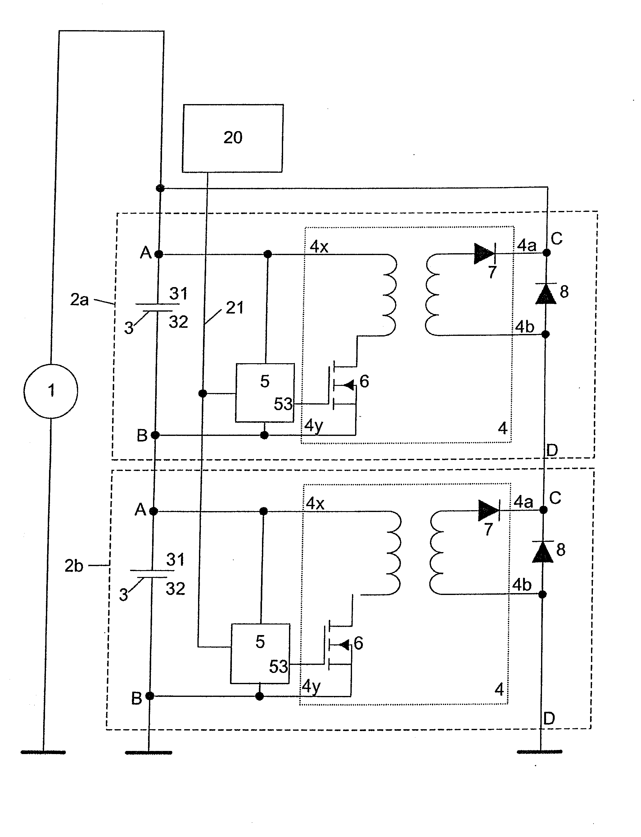
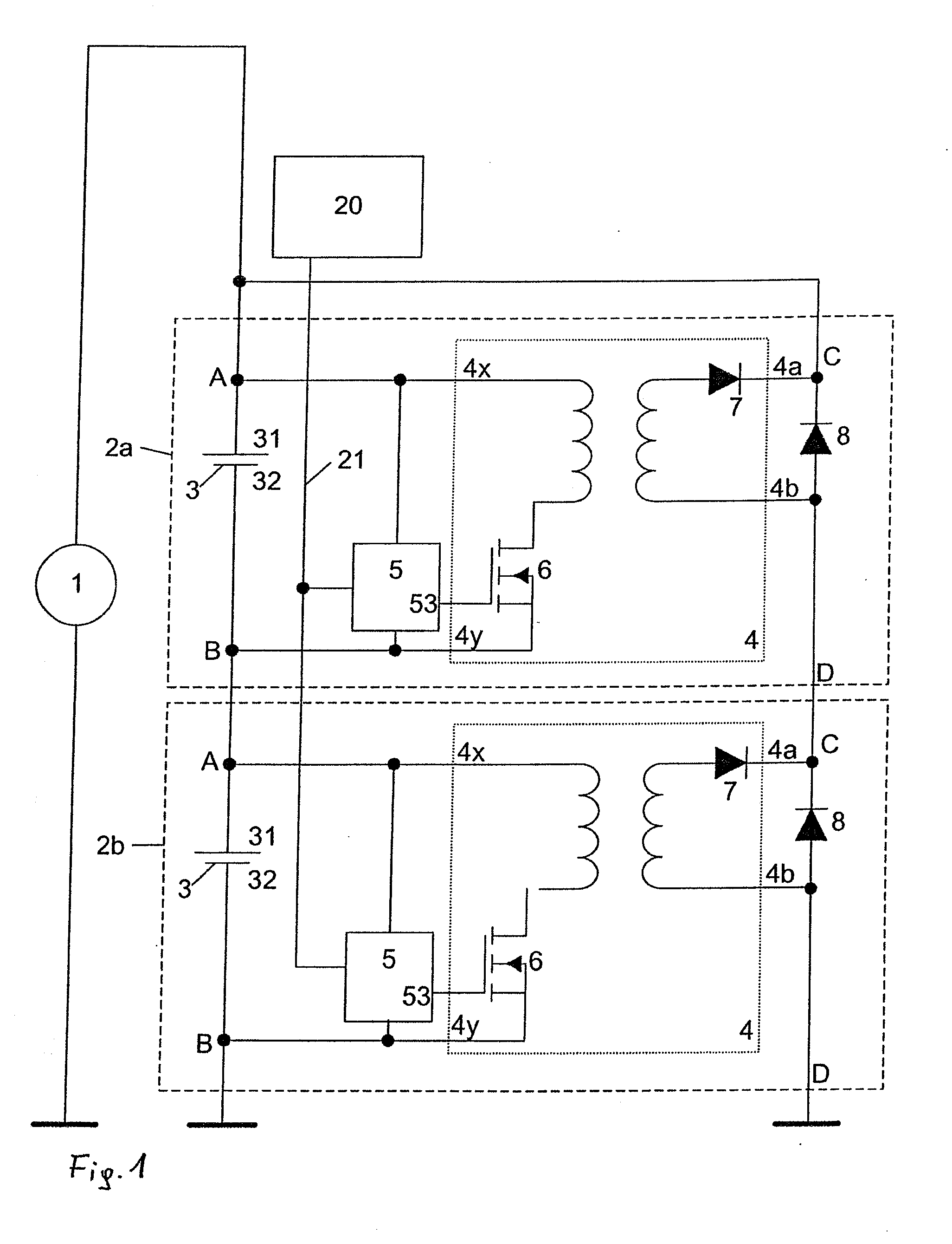
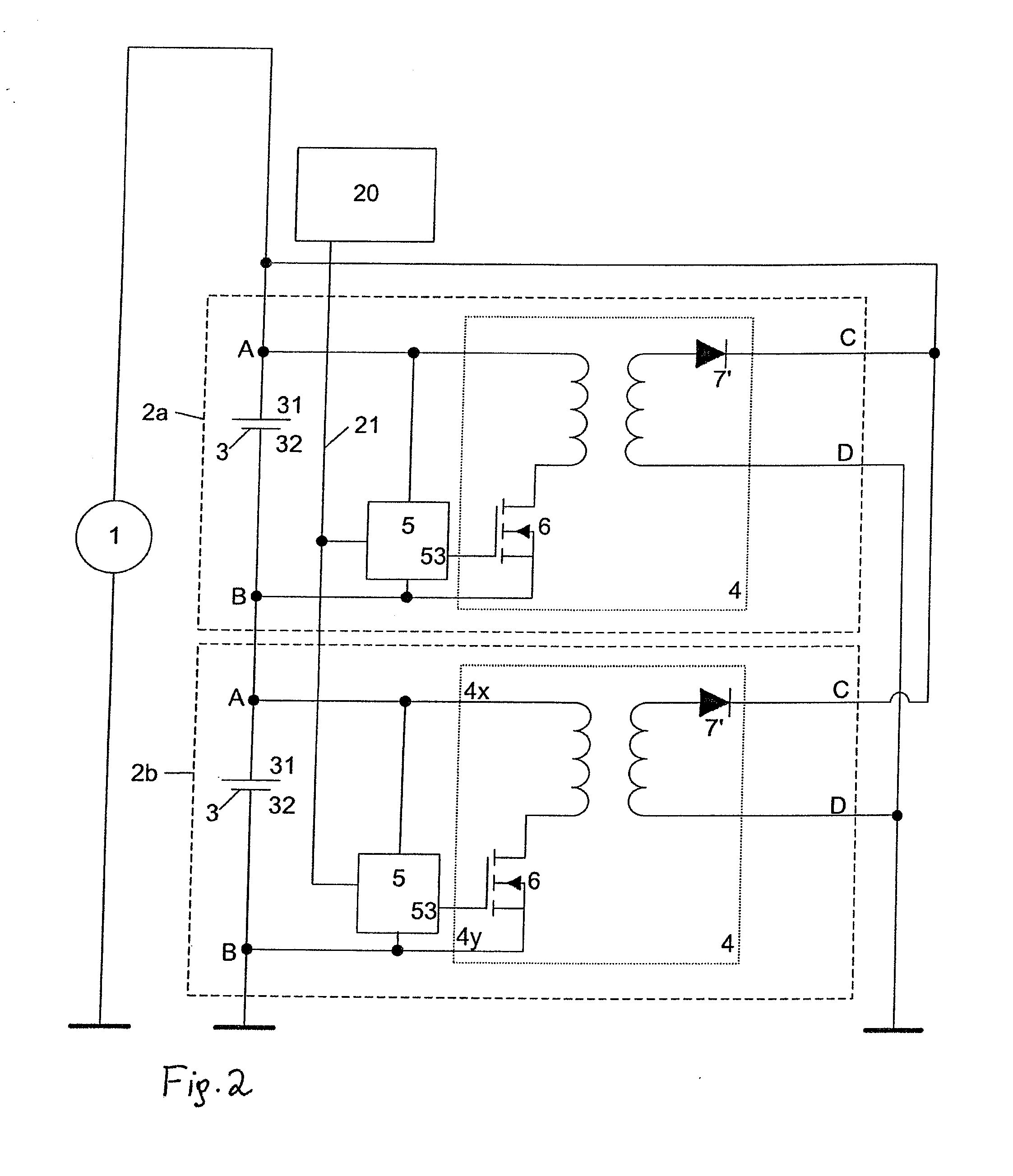
[0037]In FIG. 1 there is depicted an embodiment of the invention. The circuit comprises two battery modules 2a, 2b which are connected to a charging voltage source 1. Each of the battery modules 2a, 2b comprises an energy store 3, for instance in the form of an accumulator, a battery, or a capacitor, etc. Each of the battery modules 2a, 2b comprises a first connection A and a second connection B. Furthermore, each of the battery modules 2a, 2b comprises a first compensation connection C as well as a second compensation connection D. The energy store 3 is connected at the positive connection 31 of the energy store 3 to the first connection A and at the negative connection 32 of the energy store 3 to the second connection B. Each of the ends of the series connection of the energy stores 3 will be connected to one of the poles of the charging voltage source 1, respectively, or to one connection of a consumer load, respectively. In doing so, by the charging voltage source 1 the voltage ...


PUM


Abstract

A battery module and an arrangement including a number of battery modules connected in series are disclosed. An energy store has a positive and a negative connection. A boost converter has a first and a second converter output. The energy store is connected at the positive connection of the energy store to a first connection and at the negative connection of the energy store to a second connection. The first converter output is connected to a first compensation connection and the second converter output is connected to a second compensation connection. The converter is designed to draw energy from the energy store and to provide the energy to the converter outputs of the converter in the form of current.

Description

[0001]This application is a continuation of co-pending International Application No. PCT / AT2011 / 000287, filed Jun. 30, 2011, which designated the United States and was not published in English, and which claims priority to Austrian Patent Application No. A 1129 / 2010, filed Jul. 2, 2010, both of which applications are incorporated herein by reference.TECHNICAL FIELD[0002]The invention relates to a battery module.BACKGROUND[0003]According to prior art there are known arrangements of battery modules wherein the battery modules each comprise an energy store. The battery modules are connected in series, and a predetermined current is applied to them by a charging device. In the course of the charging process the problem exists that the individual energy stores are charged differently due to the different ageing properties, and that an undesirable overcharging of individual energy stores can occur until the required charging voltage of the arrangement as a whole is reached.[0004]To this e...

Claims


Application Information

Patent Timeline
Patent Type & Authority Applications(United States)
IPC IPC(8): H02J7/00H02M3/335
CPCB60L11/1866H02J7/0014Y02T10/7005Y02T10/7061H02J7/0065H02M3/33507Y02T10/92B60L58/22Y02T10/70H02J2207/20
Inventor GOLLOB, PETERROESSLER, WERNERPECHLANER, ANDREAS
Owner INFINEON TECH AUSTRIA AG
Why Eureka
Try Eureka