System For Real-Time Surveillance Of Production Facility And Environmental Conditions

a production facility and environmental monitoring technology, applied in the field of real-time surveillance of production facilities, can solve the problems of labor costs, unsatisfactory manual examination and visual inspection, and the inability to meet the requirements of today, and achieve the effect of reducing machine failure rate and simplifying communication cable connection

Inactive Publication Date: 2010-01-07
LIANZHUN TECH +2
View PDF6 Cites 21 Cited by
  • Summary
  • Abstract
  • Description
  • Claims
  • Application Information

AI Technical Summary

Benefits of technology

[0005]A primary object of the present invention is to provide a system for real-time surveillance of production facility and environmental conditions, which operation state and operation data from multiple production lines may be collected in real time by controllers provided on the production lines and transmitted via a communication interface to a server for showing on a surveillance computer display, so that a remote manager may effectively know and control the operation state of the production lines to achieve the purpose of reducing labor and manufacturing costs, upgrading production efficiency, and improving product quality.
[0006]Another object of the present invention is to provide a system for real-time surveillance of production facility and environmental conditions, in which a plurality of machine surveillance controllers are serially connected to simplify the communication cable connection among production lines and facilitate the maintenance of the production lines.
[0008]To enable simplified communication cable connection in the production lines, the machine surveillance controllers within the same one machine surveillance group are connected to one another by using a physical line to serially connect to the CANBUS unit in each of the machine surveillance controllers, and the physical line is connected at one end of the surveillance host controller. With the CANBUS unit, even if any one of the serially connected machine surveillance controllers is failed, the remaining machine surveillance controllers may still send their respective surveillance data to the surveillance host controller. Meanwhile, the problem of complicated cable connection due to the provision of a communication cable between each of the machine surveillance controllers and the surveillance host controller is eliminated.
[0009]The real-time surveillance system of the present invention provides the function of data collection, so that machine operation data may be provided for reference in machine maintenance to enable preventive maintenance and reduced machine failure rate. Through a communication interface, data related to the production lines and detected by the machine surveillance controllers, including the machine operation state, production targets, and production environmental conditions on the production lines, may be transmitted via a network to the server in real time.

Problems solved by technology

Such manual examination and visual inspection are not ideal due to low accuracy thereof.
With the constantly increasing demands for upgraded product quality as well as the largely increased labor cost, the traditional manual and visual surveillance of production lines is no longer suitable for nowadays requirements.
However, with the highly automated plant process, communication cable connection between automated machines becomes so complicate that it is difficult to troubleshoot when the machines are failed.
Moreover, with the increasing growth of automated plant scale, more and more complicated surveillance apparatus are required for controlling and supervising the production lines, leading to difficulties in integrating the production information provided by the large number of surveillance apparatus.

Method used


Image

  • System For Real-Time Surveillance Of Production Facility And Environmental Conditions
  • System For Real-Time Surveillance Of Production Facility And Environmental Conditions
  • System For Real-Time Surveillance Of Production Facility And Environmental Conditions

Examples


Embodiment Construction

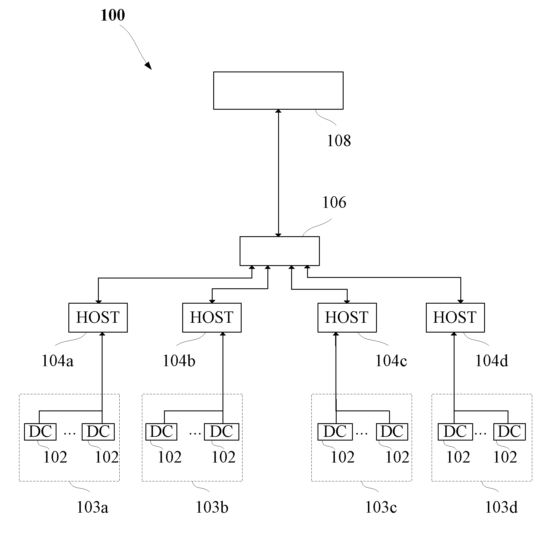
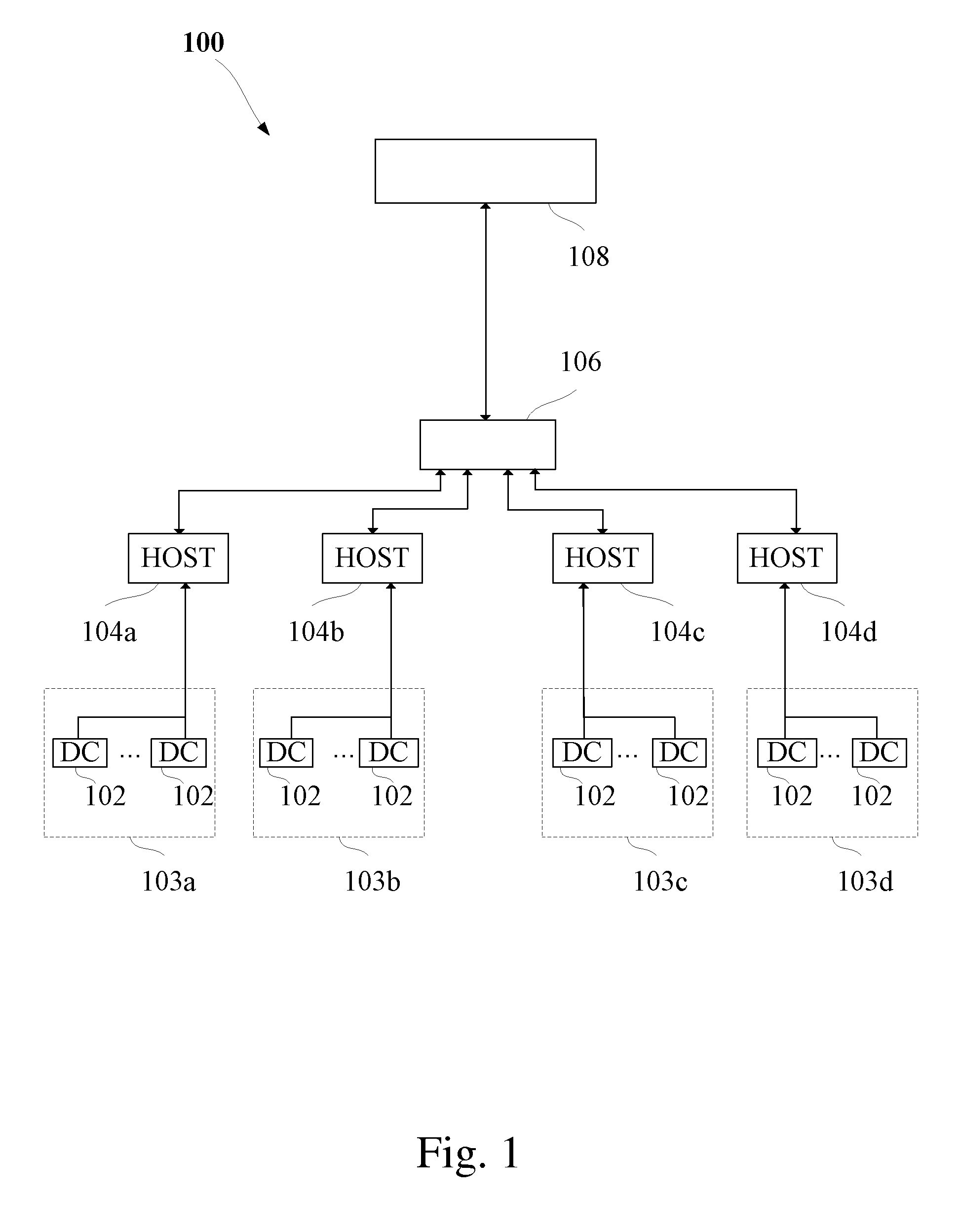
[0014]Please refer to FIG. 1 that is a system chart of a system for real-time surveillance of production facility and environmental conditions according to the present invention. For the purpose of conciseness, the system of the present invention will also be briefly referred to as the real-time surveillance system and is generally denoted by a reference numeral 100 herein. As shown, the real-time surveillance system 100 is a distributed control system (DCS) including a machine surveillance controller (DCS-DC) 102 located at each of a plurality of machines or production lines, a plurality of surveillance host controllers (DCS-HOST) 104a to 104d, a network hub 106, and a server 108. The machine surveillance controllers 102 are grouped into several machine surveillance groups 103a to 103d, each of which is independently connected to one of the surveillance host controllers 104a to 104d. It is understood the number of the machine surveillance groups 103a to 103d and of the surveillance...


PUM


Abstract

A real-time surveillance system of the present invention comprises a plurality of machine surveillance controllers for surveying a specific production line, the operation real time data of the production lines are collected and are transmitted via a communication interface to a server for showing on a surveillance display, so that a remote manager can effectively manage the operation state of production lines in order to achieve the purposes of reducing labor and manufacturing costs, upgrading production efficiency and improving product quality. The machine surveillance controllers are serially connected to simplify the communication cable connection in the production lines in order to facilitate the maintenance of production facility.

Description

FIELD OF THE INVENTION[0001]The present invention relates to a system for surveying a production site, and more particularly to a system for real-time surveillance of production facility and environmental conditions.BACKGROUND OF THE INVENTION[0002]In early-stage plant process, experienced operators are relied on to survey production lines through manual examination and visual inspection. Such manual examination and visual inspection are not ideal due to low accuracy thereof. With the constantly increasing demands for upgraded product quality as well as the largely increased labor cost, the traditional manual and visual surveillance of production lines is no longer suitable for nowadays requirements. On the other hand, in recent years, due to the upgraded performance and lowered price thereof, computers have been widely applied in plant automation systems to effectively achieve multiple benefits, including reduced labor and manufacturing costs, increased efficiency, and improved pro...

Claims


Application Information

Patent Timeline
Patent Type & Authority Applications(United States)
IPC IPC(8): G06F19/00
CPCG05B19/4063G05B2219/33273G05B2219/31467Y02P90/80
Inventor CHEN, PI-CHENLU, MEI-LUNGHUANG, CHING-CHIHYU, PING-TANG
Owner LIANZHUN TECH
Why Eureka
Try Eureka