Foot switch

a foot switch and switch technology, applied in the field of foot switches, can solve the problems of minimal trip safety and unoptimized actuation of the same, and achieve the effect of safe functional actuation

Inactive Publication Date: 2005-03-15
FERTON HLDG
View PDF16 Cites 42 Cited by
  • Summary
  • Abstract
  • Description
  • Claims
  • Application Information

AI Technical Summary

Benefits of technology

An object of the present invention is to provide a foot switch which may be designed as flat as possible for avoiding any trip danger and for guaranteeing at...

Problems solved by technology

The box shape of the foot switch results in a minimal trip safety and provides an unfavourable accessibi...

Method used


Image

  • Foot switch
  • Foot switch
  • Foot switch

Examples


Embodiment Construction

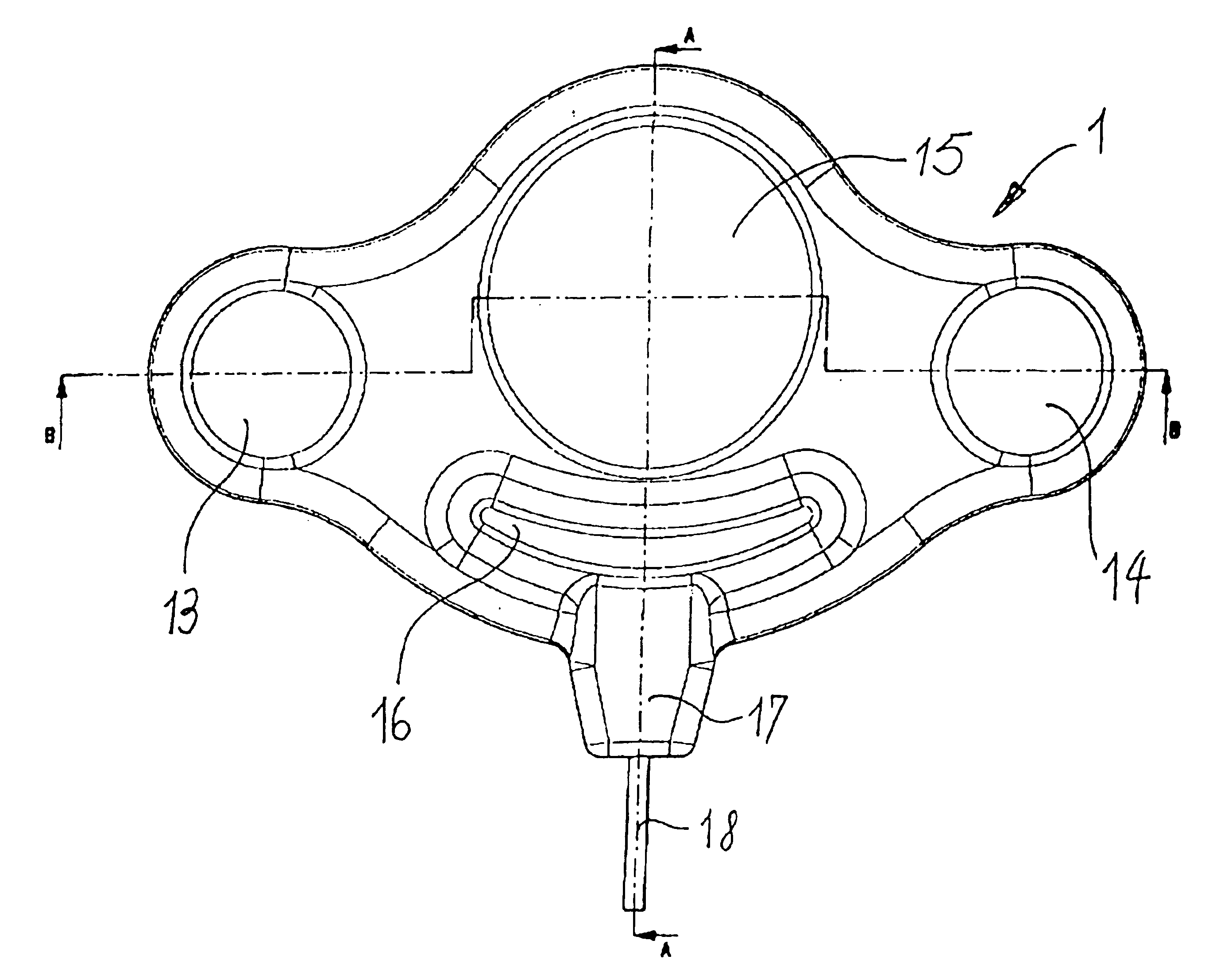
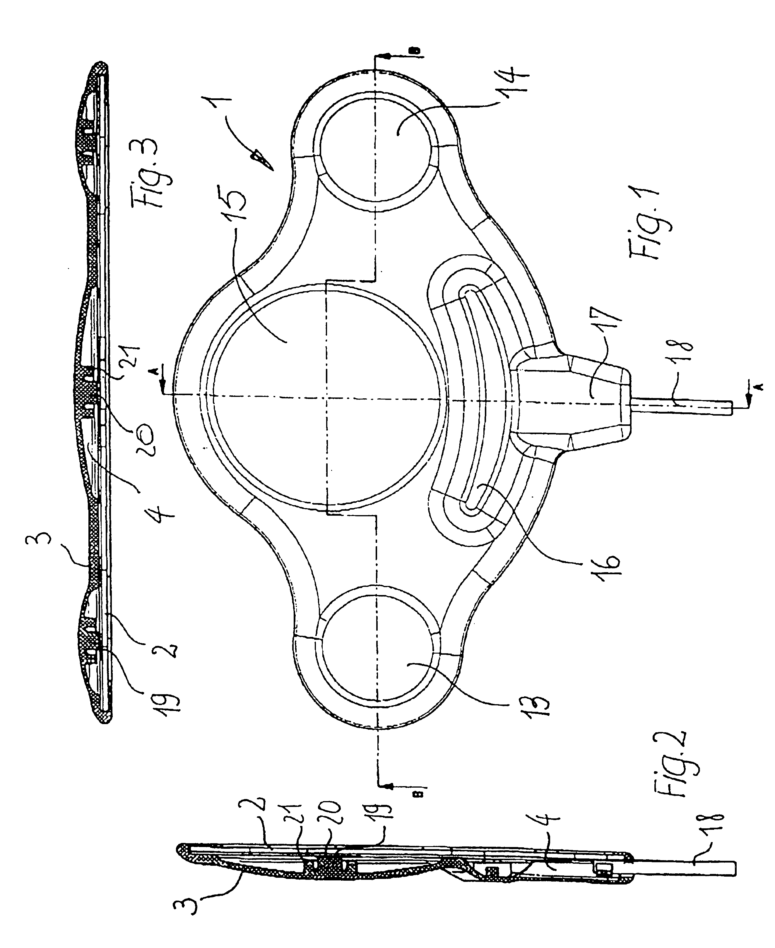
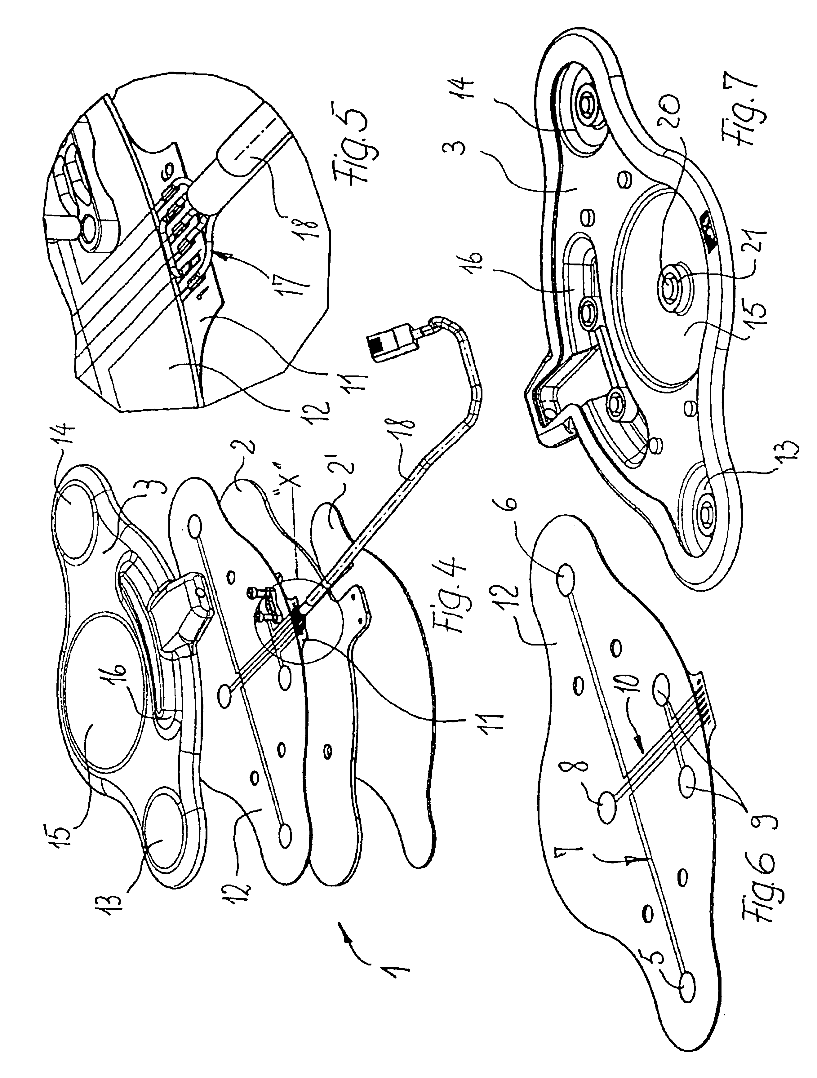
As shown by the top view in FIG. 1 a foot switch in accordance with the present invention is provided with a substantially elliptic to rectangular shape for housing a total of four electric press switches which are arranged for example for being used with a dental apparatus having a multifunctional dental handpiece which is connected with an ultrasonic power source.

The foot switch which is designated by the numeral 1 comprises a base plate 2 for supporting the foot switch on the floor at a location close to a dental apparatus which is operatively connected with the foot switch. The base plate 2 is covered by a relatively movable cover plate 3 which comprises a flexible-elastic material such as a preferred rubber-elastic material. The cover plate is fixedly connected along an edge portion with the base plate 2 in a fluid-tight manner. A space between the base plate 2 and the cover plate 3 provides a fluid-tight hollow 4. The base plate 2 is underlaid with a rubber nap plate for a sli...


PUM


Abstract

A foot switch for operation of at least two different functional members of a dental apparatus which is operatively connected with the foot switch has at least two press switches which are each formed as a diaphragm switch comprising a printed circuitry with an arrangement between two carrier foils which as a package are supported on a base plate of the foot switch within a hollow formed by an overlaid cover plate and connected by a signalling line with at least two different functional members of the dental apparatus for transmitting functional control signals upon depression of the cover plate.

Description

FIELD OF THE INVENTIONThe present invention relates to a foot switch for operation of at least two different functional members of a dental apparatus which is operatively connected with the foot switch.BACKGROUND OF THE INVENTIONA prior art foot switch of the kind as herein referred is described in U.S. Pat. No. 4,114,275. The foot switch is designed as a relatively flat body which has a circular base plate for supporting the foot switch on the floor at a location close to a dental apparatus. A diaphragm is fixedly connected with the base plate in a fluid-tight manner for providing a hollow which serves as a pneumatic pressure chamber of a variable volume. The diaphragm is covered with a circular cover plate which is relatively moveable to the base plate and biased upwardly by a central pressure spring. By depressing the cover plate the hollow which is surrounded by the diaphragm will be reduced in size against the biasing force of the pressure spring. A pneumatic pressure signal is...

Claims


Application Information

Patent Timeline
IPC IPC(8): A61C1/00H01H3/02H01H3/14G05G1/30H01H13/16
CPCA61C1/0023H01H3/14
Inventor BEERSTECHER, LUTZ
Owner FERTON HLDG
Why Eureka
Try Eureka