Control system for electrostatic discharge mitigation

a control system and electrostatic discharge technology, applied in the direction of cosmonautic radiation protection, transportation and packaging, cosmonautic vehicles, etc., can solve the problems of increasing the cost of launch, damaging the electronic components, and not always practical techniqu

Inactive Publication Date: 2005-03-15
THE BOEING CO
View PDF10 Cites 4 Cited by
  • Summary
  • Abstract
  • Description
  • Claims
  • Application Information

AI Technical Summary

Benefits of technology

One advantage of the invention is that the heaters provided in the present invention may be implemented in a relatively light manner. That is, the heaters included in the present invention will minimally affect the payload capacity and payload volume.
Other advantages and features of the present invention will become apparent when viewed in light of the detailed description of the preferred embodiment when taken in conjunction with the attached drawings and appended claims.

Problems solved by technology

Whenever the electron flux level exceeds a threshold that causes the induced electric field to exceed the dielectric breakdown strength, electrostatic discharges occur which may damage the electronic components.
This technique is not always practical because the thermal properties and RF transmission characteristics may be adversely affected by the conductive coating.
Increasing the weight increases the costs of launch and may reduce the mass usable for a payload.

Method used


Image

  • Control system for electrostatic discharge mitigation
  • Control system for electrostatic discharge mitigation
  • Control system for electrostatic discharge mitigation

Examples


Embodiment Construction

In the following figures the same reference numerals will be used to identify the same components. The present invention is described with respect to a satellite. However, the present invention has various other applications including space-based applications and non space-based applications.

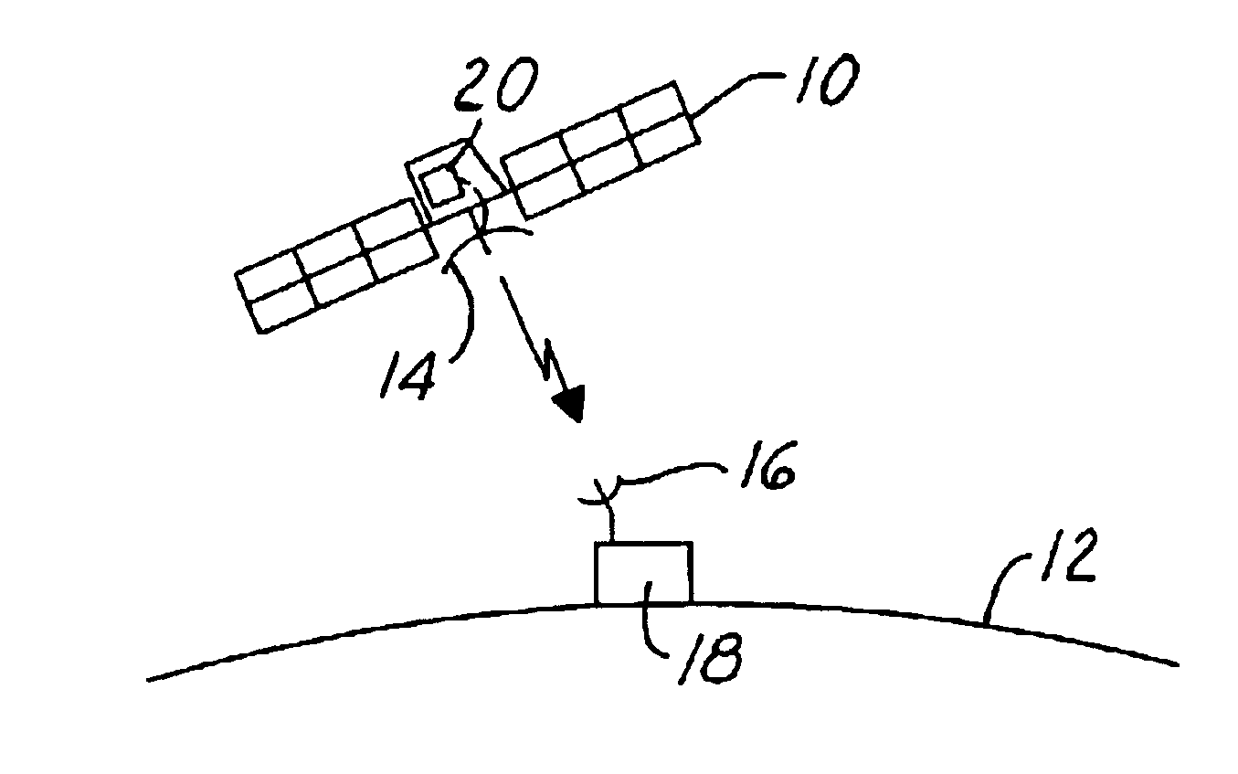
Referring now to FIG. 1, a satellite 10 is illustrated above earth 12. Satellite 10 has an antenna 14 that is used to communicate with an antenna 16 on a ground station 18. Satellite 10 includes a control circuit 20 according to the present invention. Control circuit 20 may be incorporated on to various types of telemetry, command, and control circuits. Control circuit 20 may actually be incorporated into such circuits.

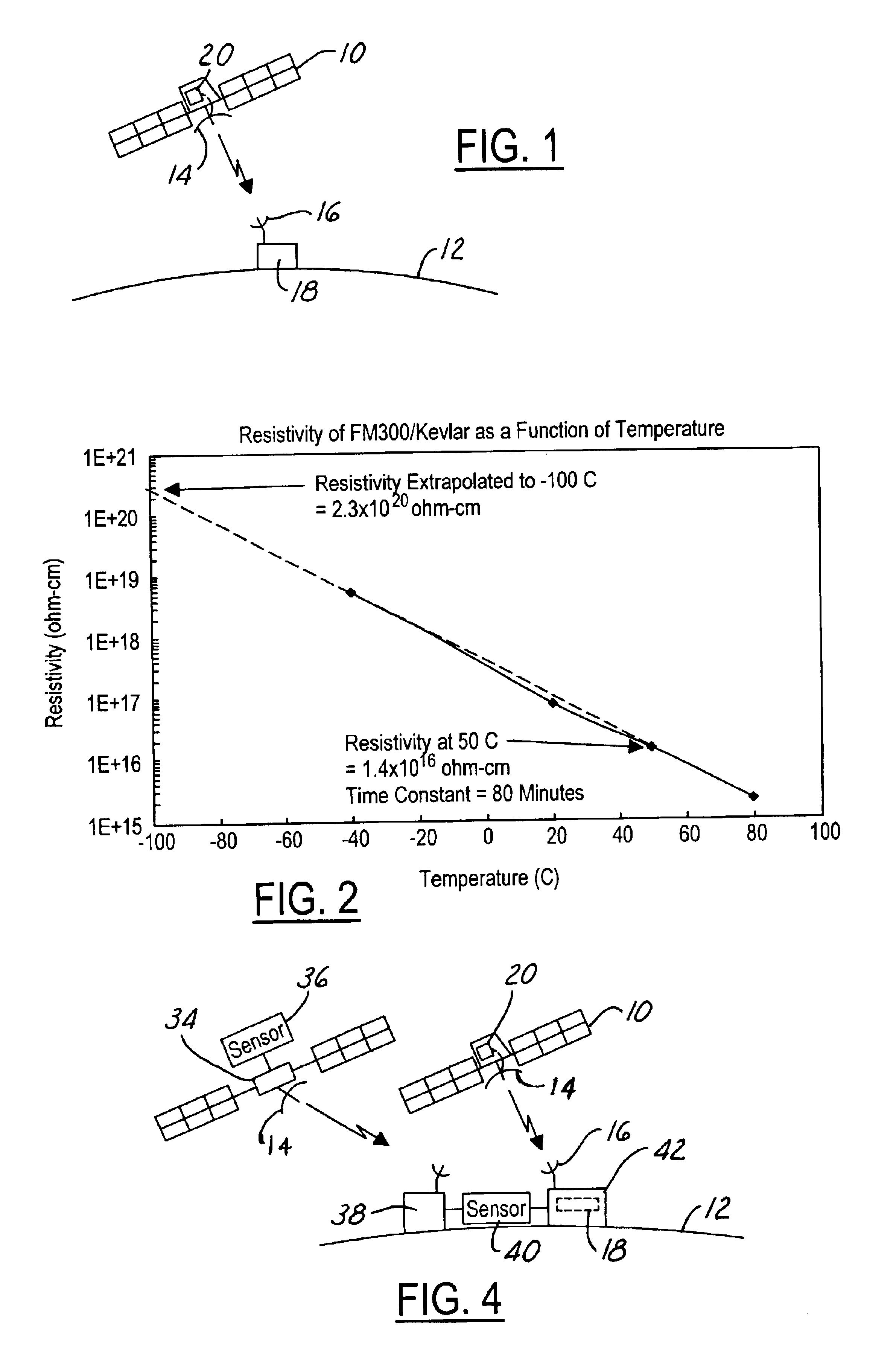
Referring now to FIG. 2, as mentioned above, the spacecraft environment is typically quiet in terms of electron flux levels. However, when the electron flux levels increase the electric field may increase and cause breakdown of the non-conductive material. As illustrated in FIG. 2...


PUM


Abstract

A control circuit (20) for controlling electrostatic discharge in an electric component includes a heater (28) that is thermally coupled to the component. A sensor (30) is used for sensing a sensed condition. A controller is coupled to the heater and the sensor. The controller (24) heats the component in response to the sensed condition. The sensor (30) may include an electron flux level near the component or a surface potential of the component itself.

Description

TECHNICAL FIELDThe present invention relates generally to dielectric components, and more particularly, to charge mitigation for use with the electronic components that is particularly useful in a spacecraft environment.BACKGROUND ARTElectrical components are typically mounted on a non-conductive or dielectric material. Such devices are often used in a space environment. Usually the space environment is quiet in terms of the electron flux level. Thus, the electric field stays below a dielectric breakdown level of the non-conductive material. At certain times, however, the electron flux and corresponding electric field may increase. The electric field (E) within a non-conductive material is directionally proportional to the product of the resistivity of the material (ρ) and the incident electron flux level (J). That is, E=ρJ. Whenever the electron flux level exceeds a threshold that causes the induced electric field to exceed the dielectric breakdown strength, electrostatic discharge...

Claims


Application Information

Patent Timeline
Patent Type & Authority Patents(United States)
IPC IPC(8): B64G1/54B64G1/22
CPCB64G1/546
Inventor BODEAU, JOHN MICHAELLEUNG, PHILIP L.
Owner THE BOEING CO
Why Eureka
Try Eureka