
Demodulation apparatus for digital audio amplifier

a digital audio amplifier and demodulation apparatus technology, applied in the field can solve the problems of limited space, high cost, heat generation of digital audio amplifiers, etc., and achieve the effect of reducing costs and minimizing space and heat generation

Inactive Publication Date: 2005-03-15
ABOV SEMICON
View PDF1 Cites 0 Cited by
  • Summary
  • Abstract
  • Description
  • Claims
  • Application Information

AI Technical Summary

Benefits of technology

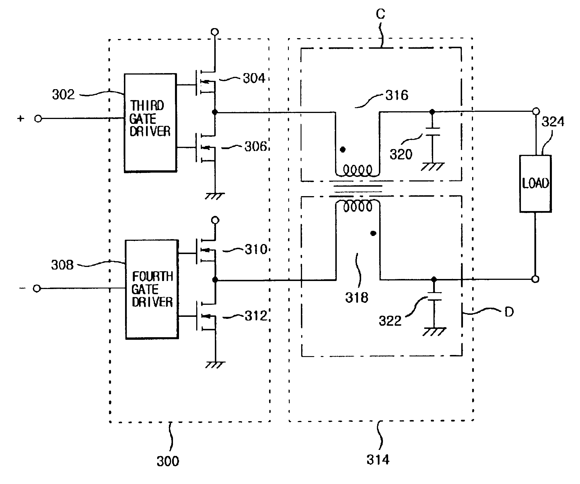
The present invention is a demodulation apparatus for a digital audio amplifier that solves problems of limited space, high costs, and heat generation. It uses a paired inductor to minimize space and heat generation, which decreases costs. The apparatus includes a first inductor, a second inductor, a first capacitor, and a second capacitor. The first inductor is connected between a positive digital audio signal output terminal and one end of a load, while the second inductor is connected between a negative digital audio signal output terminal and the other end of the load, and magnetically coupled to the first inductor. The first capacitor is connected between the one end of the load and ground, and is coupled to the first inductor for serving as a low-pass filter. The second capacitor is connected between the other end of the load and ground, and is connected to the second inductor for serving as a low-pass filter. The technical effects of this invention are that it reduces space and heat generation, decreases costs, and improves the quality of digital audio amplification.

Problems solved by technology

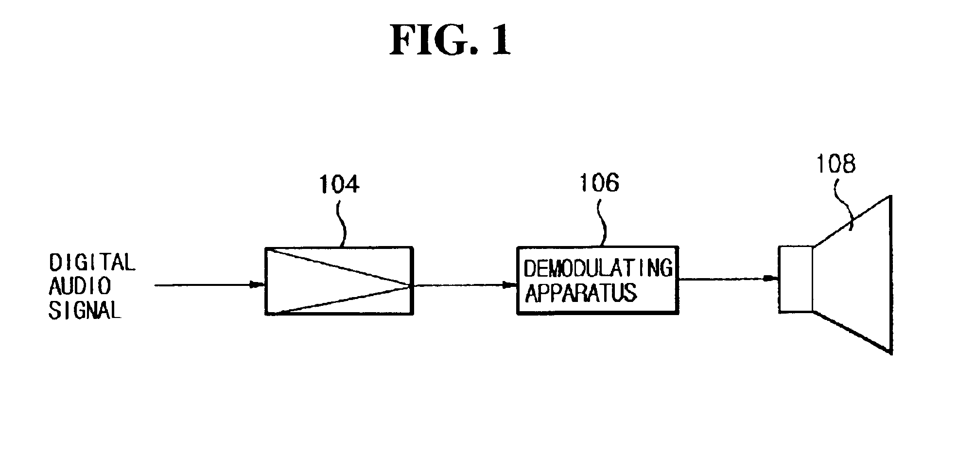
Since the demodulation apparatus 106 employed in the digital audio amplifier includes a plurality of inductors L1 and L2, problems exist in terms of limited space, high costs, and heat generation in the digital audio amplifier.

Method used


Image

  • Demodulation apparatus for digital audio amplifier
  • Demodulation apparatus for digital audio amplifier
  • Demodulation apparatus for digital audio amplifier

Examples


Embodiment Construction

Reference will now be made in detail to the preferred embodiment of the present invention, an example of which is illustrated in the accompanying drawings.

A demodulation apparatus for a digital audio amplifier according to one preferred embodiment of the present invention will now be described with reference to FIG. 4.

The demodulation apparatus 314 is composed of two low-pass filters, third low-pass filter C and fourth low-pass filter D. The third low-pass filter C includes a third inductor 316 interposed and connected between a positive digital audio signal output terminal and one end of a load 324, and a third capacitor 320 interposed and connected between one end of the load 324 and the ground. The third low-pass filter C demodulates a positive digital audio signal into an analog audio signal to output the result to one end of the load 324.

The fourth low-pass filter D includes a fourth inductor 318, which is interposed and connected between a negative digital audio signal output ...


PUM


Abstract

Disclosed is a demodulation apparatus for a digital audio amplifier capable of solving a space, cost and heat generation of the digital audio amplifier. The demodulation apparatus includes a first inductor connected between a positive digital audio signal output terminal and one end of a load, a second inductor connected between a negative digital audio signal output terminal and the other end of the load, and magnetically coupled to the first inductor, a first capacitor connected between the one end of the load and ground and coupled to the first inductor for serving as a low-pass filter, and a second capacitor connected between the other end of the load and ground and connected to the second inductor for serving as a low-pass filter.

Description

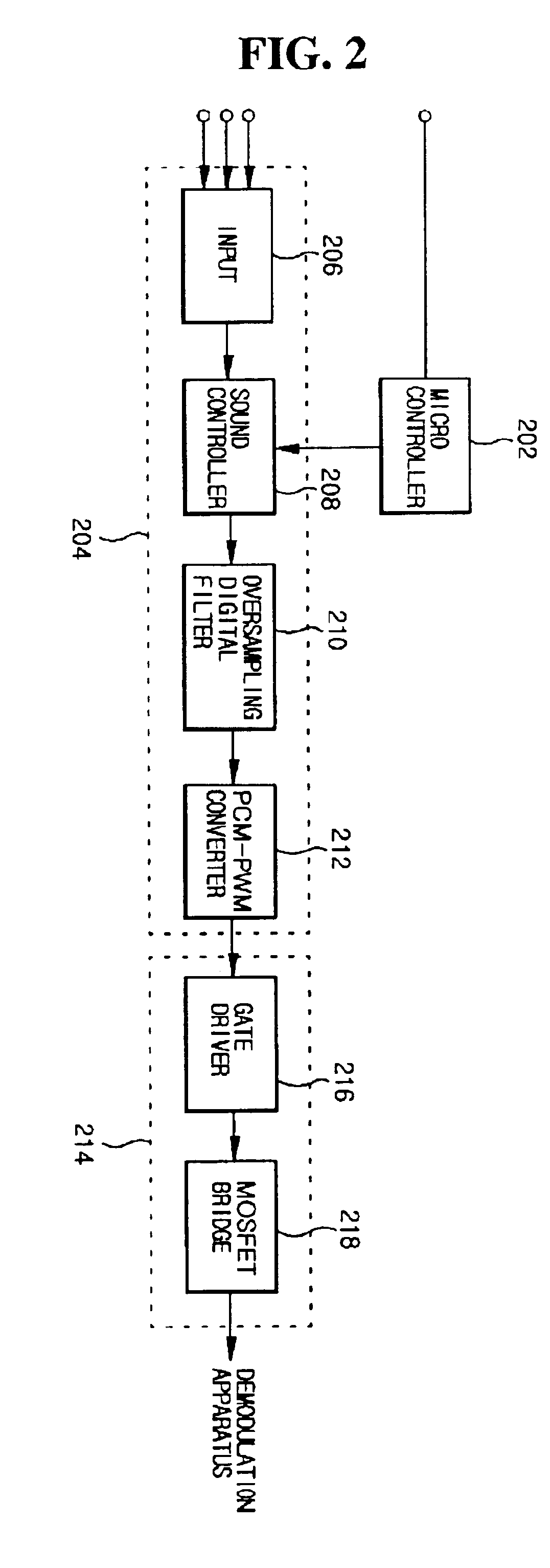
BACKGROUND OF THE INVENTION1. Field of the InventionThe present invention relates to a digital audio amplifier, and more particularly, to a demodulation apparatus for a digital audio amplifier.2. Description of the Related ArtGenerally, the purpose of a digital audio amplifier is to minimize distortion of a signal and to output high fidelity audio signals by digitally processing a received audio signal.Referring to FIG. 1, which indicates a block diagram of a conventional digital audio amplifier, a digital audio amplifier 104 receives a digital audio signal and amplifies it in a digital state.As shown in FIG. 2, the digital audio amplifier 104 includes a micro controller 202, a digital audio signal conversion section 204, and an amplification output section 214. The micro controller 202 controls a sound controller 208 of the digital audio signal conversion section 204 so as to provide effective acoustic control.An input section 206 of the digital audio signal conversion section 204 ...

Claims


Application Information

Patent Timeline
Patent Type & Authority Patents(United States)
IPC IPC(8): H03H7/09H03C1/00
CPCH03H7/09H03H2001/0035H03C1/00
Inventor JEONG, BONG SOO
Owner ABOV SEMICON
Learn More