Automated on-site meter registration confirmation using a portable, wireless computing device

a wireless computing device and automatic metering technology, applied in the field of metering and metering systems, can solve the problems of increasing the complexity of both the metering device and the installation process, increasing the complexity of the metering device, and increasing the complexity of the back-office business process

Inactive Publication Date: 2005-03-15
ELSTER ELECTRICTY LLC
View PDF229 Cites 195 Cited by
  • Summary
  • Abstract
  • Description
  • Claims
  • Application Information

AI Technical Summary

Problems solved by technology

Although the data collection and reporting processes have evolved with the advancement in metering technologies, the meter installation process has continued to be a painstaking, labor-intensive, paper-based process rife with the potential for human error.
As the metering devices have become more sophisticated with many configurable options, the back-office business processes also have increased in sophistication and complexity.
The increase in complexity of both the metering devices and the back-office business processes, have combined to significantly increase the potential for human error in the labor-intensive, paper-based meter installation process.
In particular, today a meter installer typically leaves the installation site without having received a positive confirmation that the meter was properly installed and correctly configured to support the desired back-office business processes.
As with any segregated process, the logistics of such verification are plagued by various complications including scheduling and ownership.
Even if the installer is able to speak directly with the operator, for example with a portable telephone, the installer cannot visually perceive what occurs at the remote network location, nor can the operator see what occurs on-site at the meter location.
This manual process is further complicated by today's era of utility deregulation that ofen divides the installation process among multiple, separate entities.

Method used


Image

  • Automated on-site meter registration confirmation using a portable, wireless computing device
  • Automated on-site meter registration confirmation using a portable, wireless computing device
  • Automated on-site meter registration confirmation using a portable, wireless computing device

Examples


Embodiment Construction

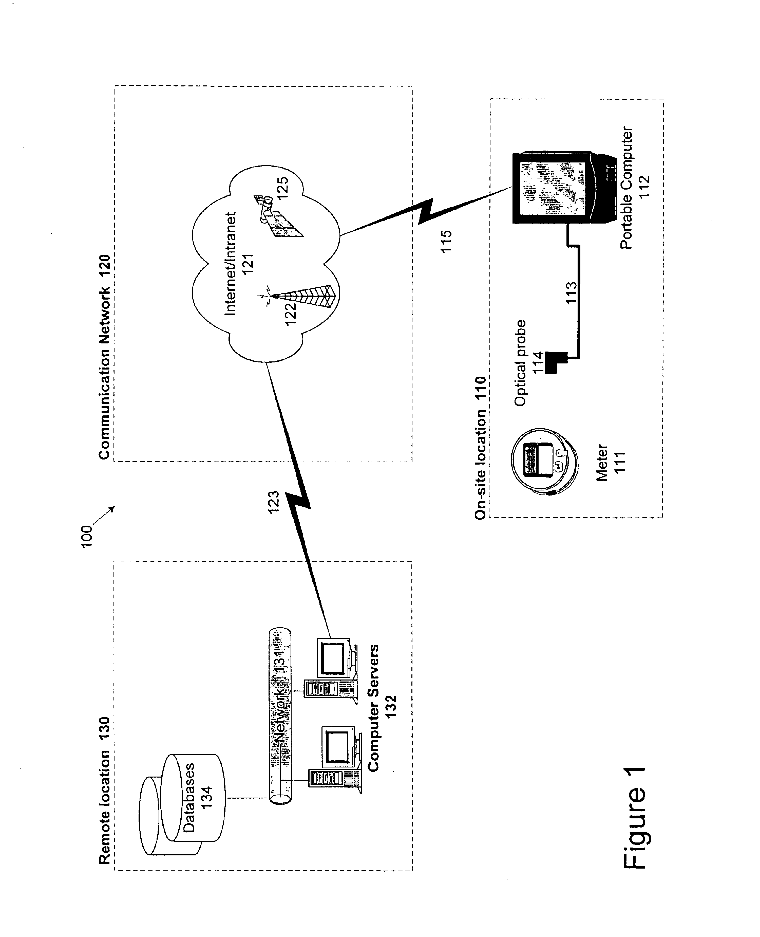
FIG. 1 is a block diagram of a system 100 for immediately verifying an installation of a non-communicative meter 111. Although meter 111 is shown in FIG. 1 as an electric power meter, it should be appreciated that system 100 may include any type of meter including, for example, an electrical power meter, a gas meter, and / or a water meter. Similarly, although other components are shown in FIG. 1, it should be appreciated that the invention is not limited to the components shown in FIG. 1, but are provided for the purposes of illustrating an embodiment of the invention.

As shown in FIG. 1, system 100 may include an on-site location 110, a remote location 130, and a communication network 120. Although not shown specifically in FIG. 1, a power line for a metered service provided by a distribution or transmission portion of a power system, for example, provides power to meter 111. As is well known to those skilled in the art, meter 111 is designed to collect information on the metered ser...


PUM


Abstract

The invention is directed to a method and system for verifying an installation of an meter, for example, an electric power meter. The inventive method includes identifying the electric power meter to a central computer using a mobile computing device. The electric power meter receives computer-executable instructions from the central computer via the mobile computing device, and transmits meter information (e.g., power consumption readings, meter identification information, and meter location) to the central computer. The meter information received from the central computer is compared with meter information available at the electric power meter. The comparison may be accomplished visually by reading the meter and comparing the readings with the information received on the mobile computing device. Also, the comparison may be accomplished automatically by the mobile computing device based on the information it receives from the central computer and the information it receives from the electric power meter.

Description

FIELD OF THE INVENTIONThe invention generally relates to the field of metering and metering systems. More particularly, the invention relates to verifying the proper installation, configuration, and communication connectivity of meters.BACKGROUND OF THE INVENTIONSince its infancy, meters have been used to capture usage information for billing, load survey, and other purposes. Meters have progressed from simple electromechanical devices that require human meter readers to more sophisticated electronic meters that can be equipped with remote communication options. These electronic meters typically have computer processors capable of capturing and storing more detailed data and transmitting this data over communication networks to a remote computer network. The remote computer network collects, processes, and stores this metered data to support different back-office business processes like billing, load survey, customer service, and automated meter reading (AMR) to name a few.Although ...

Claims


Application Information

Patent Timeline
Patent Type & Authority Patents(United States)
IPC IPC(8): H04Q9/00
CPCH04Q9/00H04Q2209/60H04Q2209/40
Inventor KELLEY, RAYMOND HSUTTON, III, JOHN C.BRUCE, DONNA L.ARDALAN, SASAN H.
Owner ELSTER ELECTRICTY LLC
Why Eureka
Try Eureka