
Transceiver for a wireless optical telecommunication system

a wireless optical telecommunication system and transceiver technology, applied in optics, instruments, electrical equipment, etc., can solve the problems of increasing the footprint, contributing to the overall size or “footprint” of the unit, and the individual parts themselves may also have a large footprin

Inactive Publication Date: 2005-03-15
PERTEX TELECOMM
View PDF22 Cites 19 Cited by
  • Summary
  • Abstract
  • Description
  • Claims
  • Application Information

AI Technical Summary

Problems solved by technology

These optical transmitter and receiver units may have many parts, thereby contributing to the overall size or “footprint” of the units.
The individual parts themselves may also have a large footprint.
This increased footprint can be detrimental in situations where the units need to be installed in a non-obtrusive manner.
The increased footprint can also disadvantageously limit the amount of available space, within the housing of the transmitter or receiver units, in which to fit the various parts or components.
These optical transmitter and receiver units can also be difficult to align properly during installation and during use.
Furthermore, the various optics and components of typical optical transmitters and optical receivers are heavy, fragile, bulky, and difficult to manufacture with consistent quality, and are often expensive.

Method used


Image

  • Transceiver for a wireless optical telecommunication system
  • Transceiver for a wireless optical telecommunication system
  • Transceiver for a wireless optical telecommunication system

Examples


Embodiment Construction

Embodiments of a transceiver that can be used in a wireless optical telecommunication system are described in detail herein. In the following description, numerous specific details are provided in order to provide a thorough understanding of embodiments of the invention. One skilled in the relevant art will recognize, however, that the invention can be practiced without one or more of the specific details, or with other methods, materials, components, etc. In other instances, well-known structures, materials, or operations are not shown or described in detail to avoid obscuring aspects of various embodiments of the invention. Furthermore, it is understood that the various embodiments shown in the figures are illustrative representations, and are not necessarily drawn to scale.

Reference throughout this specification to “one embodiment” or “an embodiment” means that a particular feature, structure, material, or characteristic described in connection with the embodiment is included in ...


PUM


Abstract

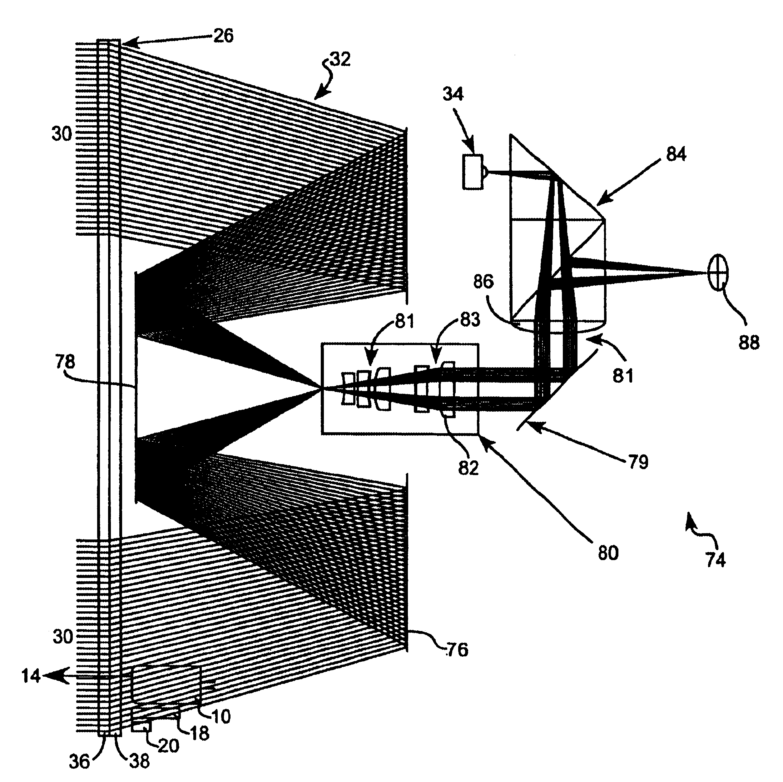
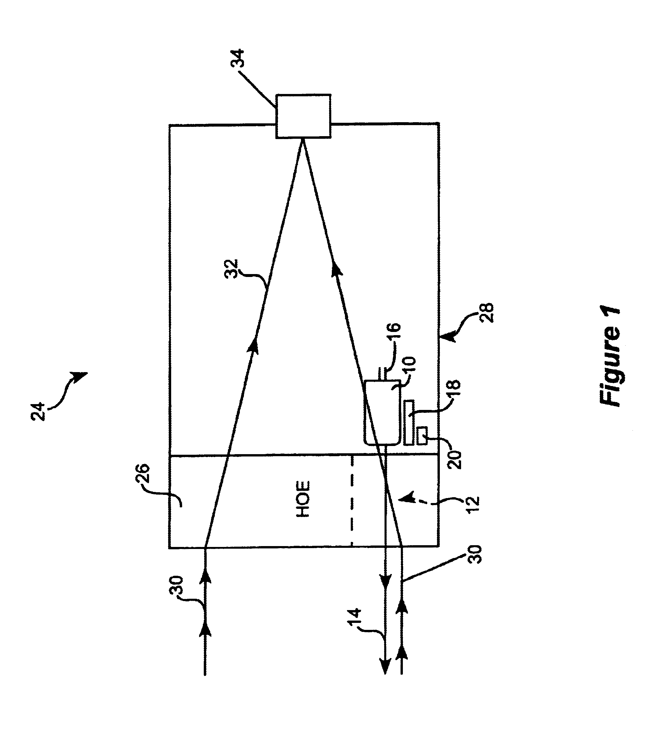
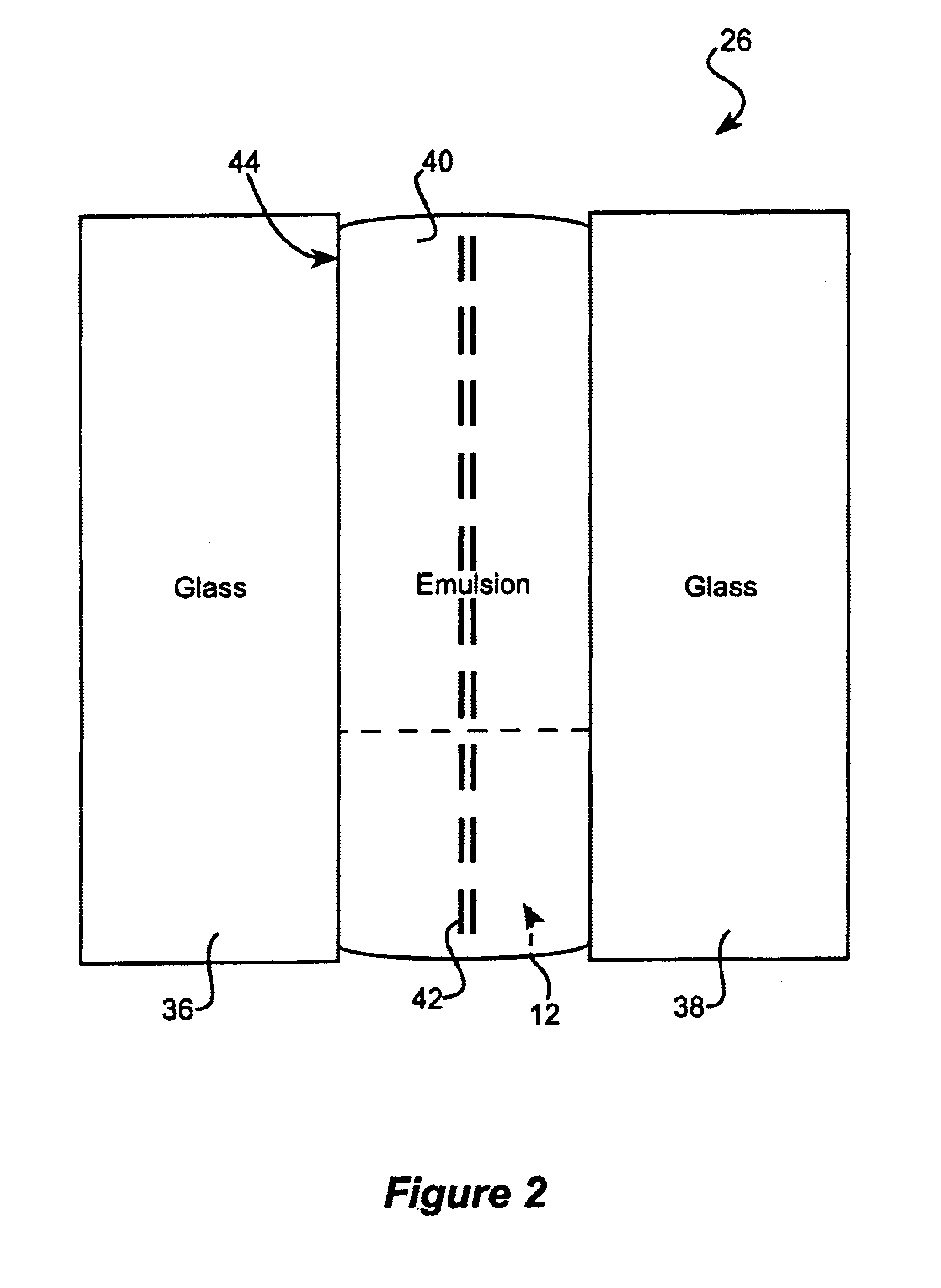
A holographic optical element (HOE) device is mounted in wireless optical telecommunication system transceiver. The HOE device includes a developed emulsion material having an interference pattern recorded thereon, sandwiched between a pair of elements, such as a pair of clear glass plates. In operation, the HOE device uses the recorded interference pattern to diffract received light rays towards an optical processing unit of the system receiver. A transmitter unit can be positioned at least in part behind the HOE device. An opening in the emulsion material allows a light signal transmitted from the transmitter unit to be substantially unaffected by the recorded interference pattern. The transceiver can also include a spotting scope and an alignment beacon.

Description

TECHNICAL FIELDThis disclosure relates generally to wireless optical telecommunication systems, and in particular but not exclusively, relates to a transceiver that is usable in a wireless optical telecommunication system.BACKGROUNDAt a basic level, a typical wireless optical telecommunication system comprises an optical transmitter and an optical receiver, with associated electronics to modulate and demodulate data on a light beam. Often, receivers are basically telescopes, while transmitters sometimes comprise units that are located separately from the receiver.These optical transmitter and receiver units may have many parts, thereby contributing to the overall size or “footprint” of the units. The individual parts themselves may also have a large footprint. This increased footprint can be detrimental in situations where the units need to be installed in a non-obtrusive manner. The increased footprint can also disadvantageously limit the amount of available space, within the housi...

Claims


Application Information

Patent Timeline
IPC IPC(8): G02B5/32
CPCG02B5/32
Inventor AMADON, CHARLES GREGORYRALLISON, RICHARD D.PRATT, MARKBAJORINS, DAVID P.STAPLETON, LAWRENCE COOPERRIDAY, RICHARD B.BROWN, HAROLD ALEXANDERLAUBY, WILLIAM JOSEPHTHOMAS, MICHAELSPARROLD, SCOTT WILLIAM
Owner PERTEX TELECOMM
Learn More