Automatic protection switch decision engine

a technology of automatic protection switch and decision engine, which is applied in the field of atms, can solve the problems of bringing down both the service path and the protection path, and the current design atm does not have the physical space for inserting the circuit board

Inactive Publication Date: 2005-03-15
LUCENT TECH INC
View PDF13 Cites 20 Cited by
  • Summary
  • Abstract
  • Description
  • Claims
  • Application Information

AI Technical Summary

Benefits of technology

An improved arrangement is attained with a very simple decision logic that, based on a comparison between two numbers that are created through the setting of bits in two registers, either directs the service line to be in the active state or in the standby state, and conversely, directs the protection li

Problems solved by technology

While an ATM constructed with I/O modules as shown in FIG. 1, and employed in the manner described above, is able to circumvent problems that originate in the fiber or the LIU, it nevertheless has a significant weakness.
Consequently, a general failure in the I/O module brings down both the service path and the pro

Method used


Image

  • Automatic protection switch decision engine
  • Automatic protection switch decision engine
  • Automatic protection switch decision engine

Examples


Embodiment Construction

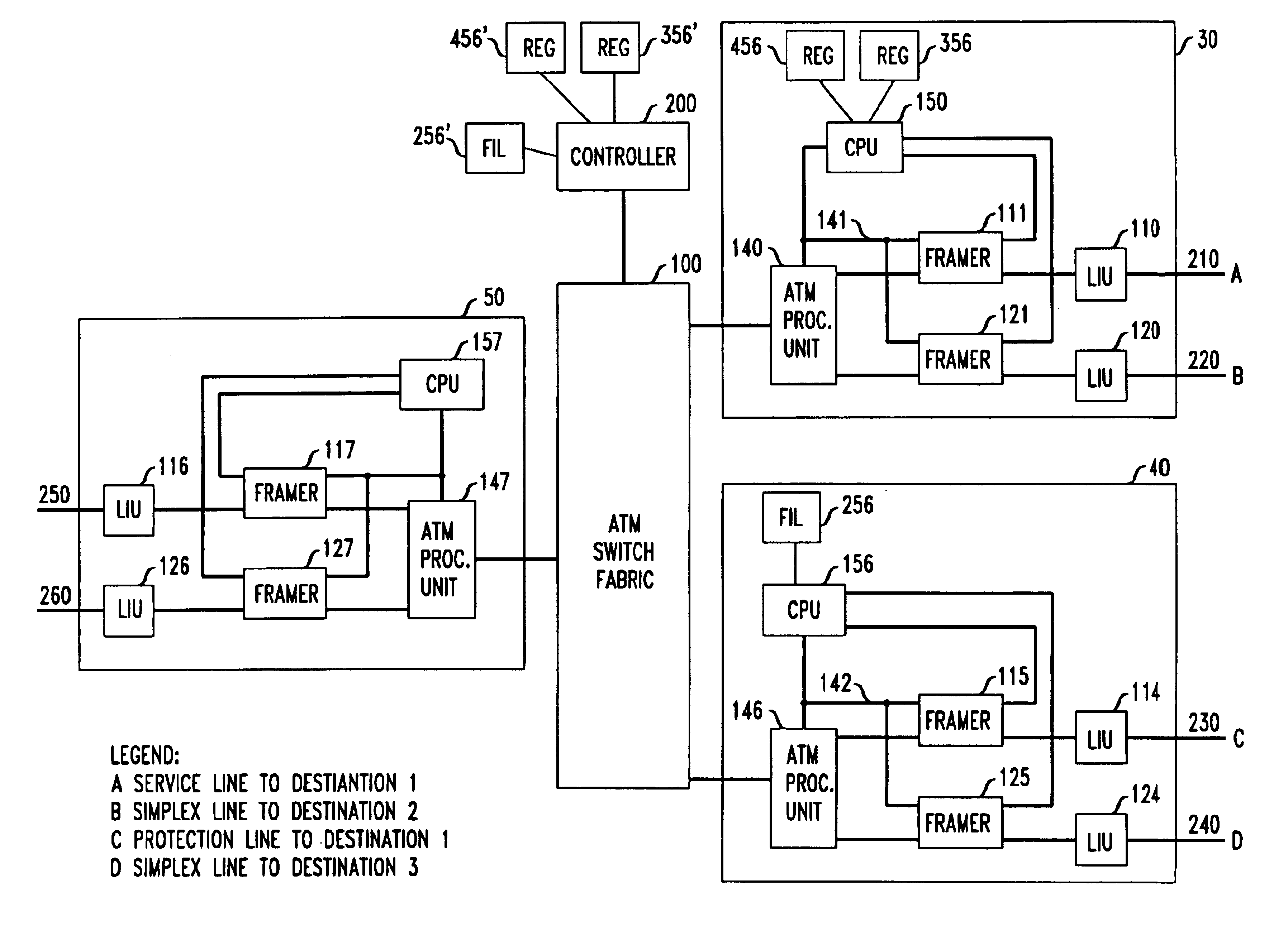
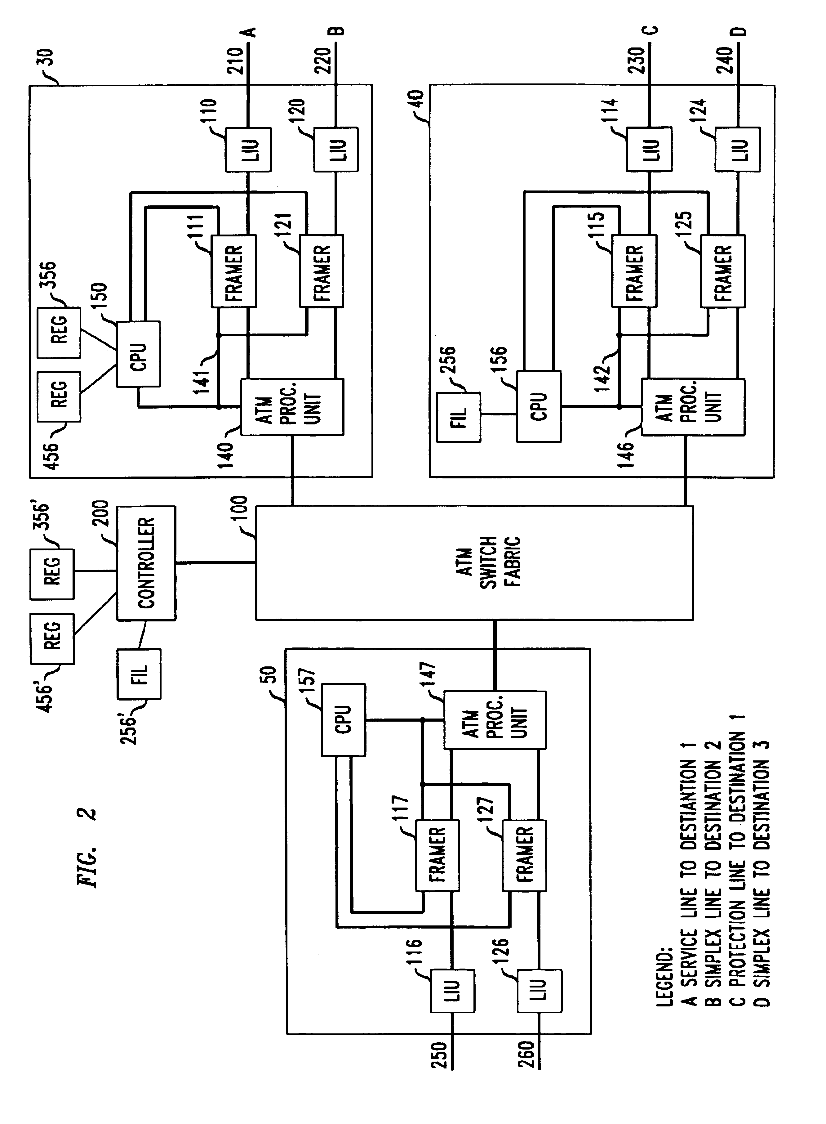
FIG. 2 presents an illustrative ATM arrangement where the protection line and the service line are connected to different I / O modules. It shows an ATM switch 100 and associated I / O modules 30, and 40 and 50. Modules 30-50 differ from module 10 in that APS switch unit 130 is effectively not found in these modules. Illustratively, FIG. 2 has one duplex span to the right of ATM switch 100 that includes a service line and a protection line, and two simplex spans that do not have protection lines. To the left of ATM switch 100 there are two simplex spans. The service line of the duplex span is connected from I / O module 30 to destination 1 via fiber 210. The protection line of the duplex span is connected from I / O module 40, also to destination 1, via fiber 230. Fiber 220 is connected to LIU 120 of I / O module 30 and it forms a simplex span to a destination 2. Similarly, fiber 240 is connected to LIU 124 of I / O module 40 and it forms a simplex span to a destination 3. Fibers 250 and 260 ar...


PUM


Abstract

A decision engine decides whether to assign a service line to be active or in standby mode with a very simple decision logic that is based on a comparison between two numbers that are created through the setting of bits in two registers. The logic of the decision engine is embedded in a combination of a filter that either accepts or rejected applied stimuli, and a table that acts on accepted stimuli by the setting and resetting of bits in the two registers in accordance with a unique specification.

Description

BACKGROUND OF THE INVENTIONThis invention relates to ATMs and, more particularly to circumventing of faults in I / O modules of an ATM.FIG. 1 presents a general block diagram of a conventional local ATM switch 100 with a connected I / O module 10, and conventional remote ATM switch 200 with a connected I / O module 20 (that may be of the same construction as that of module 10). Module 10 contains a line interface unit (LIU) 110 that is connected to fiber 210, and a line interface unit 120 that is connected to fiber 220. Fiber 210 is the “service” line, in the sense that it carries live data between I / O module 10 and I / O module 20. Fiber 220 is the “protection” line, in the sense that it is ready to assume the active communication function of line 210, should fiber 210 fail. Within module 10, LIU 110 is connected to framer 111, and framer 111 is connected to APS switch unit 130. Similarly, LIU 120 is connected to framer 121, and framer 121 is connected to APS switch unit 130. APS switch 13...

Claims


Application Information

Patent Timeline
IPC IPC(8): G01R31/08H04L12/56
CPCH04L49/105H04L49/50
Inventor SHA, YUNG-CHING
Owner LUCENT TECH INC
Why Eureka
Try Eureka