Method and means for erecting a wind energy tower

a technology of wind energy and towers, applied in the field of methods and means for erecting towers, can solve the problems of high cost of customary erecting methods and hazardous lifting of tower sections by large cranes, and achieve the effect of safe use, durable and reliabl

Active Publication Date: 2005-03-22
VALMONT INDUSTIES INC
View PDF7 Cites 78 Cited by
  • Summary
  • Abstract
  • Description
  • Claims
  • Application Information

AI Technical Summary

Benefits of technology

A further object of the invention is to provide an improved wind energy tower erection device which eliminates the need for a large crane such as is customarily required.
Yet another object of the invention is to provide an improved wind energy tower erection device which may be used to erect towers having a height which exce

Problems solved by technology

The customary method of erecting the tower is quite expensive due to the requirement that the large crane must be prese

Method used


Image

  • Method and means for erecting a wind energy tower
  • Method and means for erecting a wind energy tower
  • Method and means for erecting a wind energy tower

Examples


Embodiment Construction

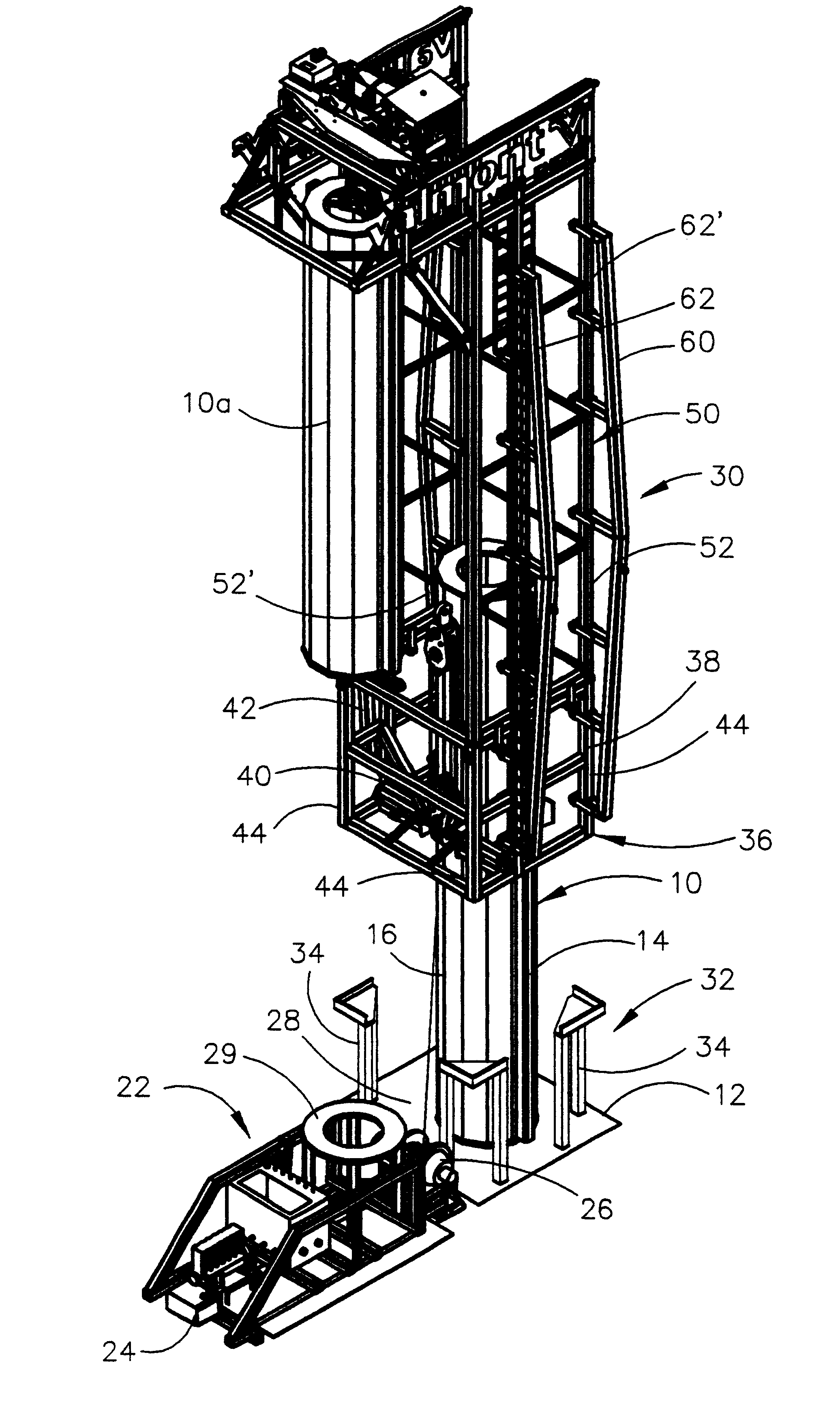
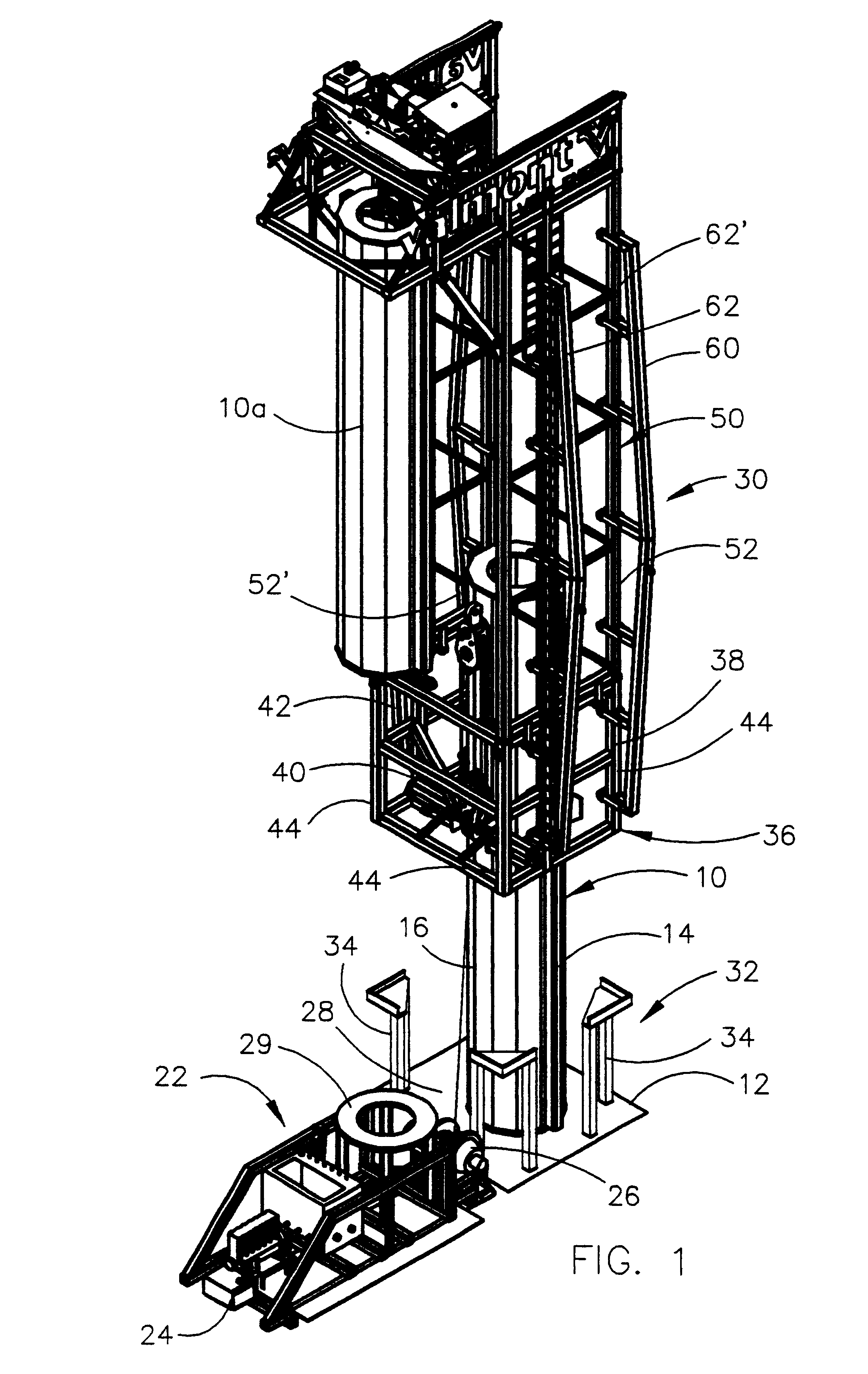
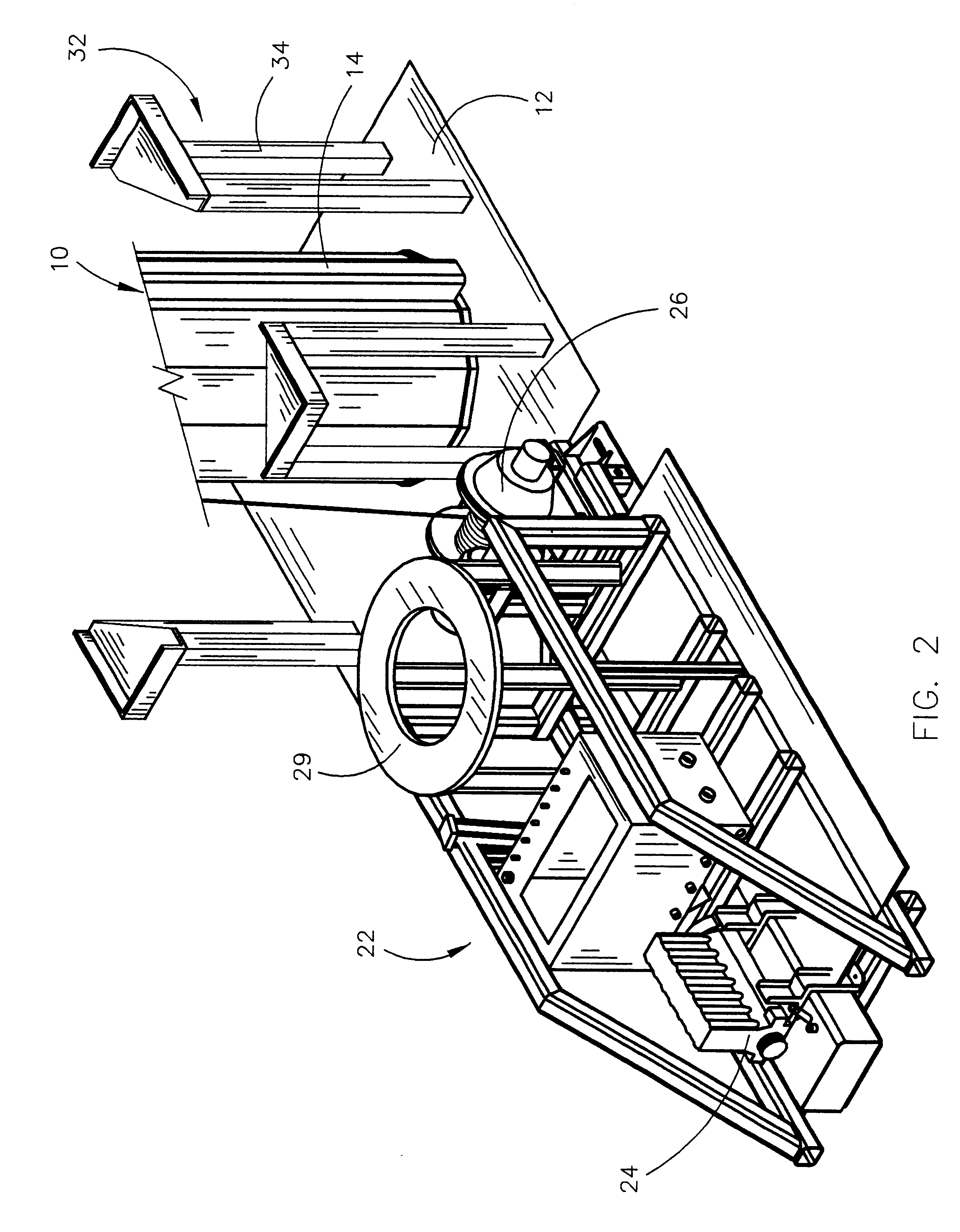
Referring to the drawings, the numeral 10 refers to a base tower section of the wind energy tower to be erected. The base tower section 10 will normally be positioned on a concrete foundation 12 by a small crane (not shown). The base tower section 10 is bolted to the foundation 12 in a conventional fashion. The base tower section 10 includes a pair of longitudinally extending rails 14 and 16 secured to the opposite sides thereof with each of the rails having vertically spaced-apart openings 18 formed therein, each of which is adapted to receive a pin 20 therein as will be described in more detail hereinafter.

Normally, the small crane will be used to mount a single base tower section on the foundation, but one or more tower sections of the tower could be mounted on the base tower section through the use of the small crane. The invention herein will be described as if a single base tower section is erected through the use of the small crane with the other tower sections of the tower b...


PUM


Abstract

A wind energy tower erection device is disclosed together with the method of assembling the same and the method of utilizing the device to erect a wind energy tower. The tower erection device successively places tower sections one upon the other until the tower is erected.

Description

BACKGROUND OF THE INVENTION1. Field of the InventionThis invention relates to a method and means for erecting a tower and more particularly to a method and means for erecting a wind energy tower wherein tower sections are successively placed upon one another.2. Description of the Related ArtWind turbines or wind energy devices are becoming more popular in the production of electrical energy. The wind turbine or wind energy device normally comprises a rotor-driven generator mounted atop a tower which may reach heights of 70 meters or more. The tower is usually comprised of a plurality of tapered or cylindrical tower sections which are secured together in an end-to-end relationship. The tower is normally erected by the use of a large crane. When the tower has been erected, the large crane lifts the turbine onto the top of the tower. The customary method of erecting the tower is quite expensive due to the requirement that the large crane must be present on the job site. Further, in som...

Claims


Application Information

Patent Timeline
IPC IPC(8): E04H12/34E04H12/00F03D1/00
CPCE04H12/34F03D1/001Y02E10/728F03D13/10Y02E10/72
Inventor PERINA, MARK J.
Owner VALMONT INDUSTIES INC
Why Eureka
Try Eureka