Fluid control apparatus

a control apparatus and fluid technology, applied in mechanical devices, valve housings, transportation and packaging, etc., can solve the problems of impaired sealing effect and device inability to finely adjust the position, and achieve the effect of reducing the number of different types of block couplings

Inactive Publication Date: 2005-03-22
FUJIKIN INC
View PDF7 Cites 33 Cited by
  • Summary
  • Abstract
  • Description
  • Claims
  • Application Information

AI Technical Summary

Benefits of technology

According to an embodiment, the device layer has a closing block for closing an upward opening of the block coupling included in the upper connecting layer, while the lower connecting layer has a support block having the same shape as one of the block couplings of the lower connecting layer and having no channel for supporting the block coupling of the upper connecting layer. This serves to reduce the number of different kinds of block couplings constituting the fluid control apparatus.

Problems solved by technology

With the conventional fluid control apparatus described, the longitudinal block couplings and the lateral block couplings are connected with screws from horizontal longitudinal directions, so that when the fluid control devices are fastened to the block couplings with screws from above, the devices can not be finely adjusted in position, and a reliable sealing effect is not always available, consequently entailing the problem that the sealing effect becomes impaired owing to deformation or strain when the apparatus is repeatedly disassembled and assembled.

Method used


Image

  • Fluid control apparatus
  • Fluid control apparatus
  • Fluid control apparatus

Examples


Embodiment Construction

An embodiment of the present invention will be described below with reference to the drawings.

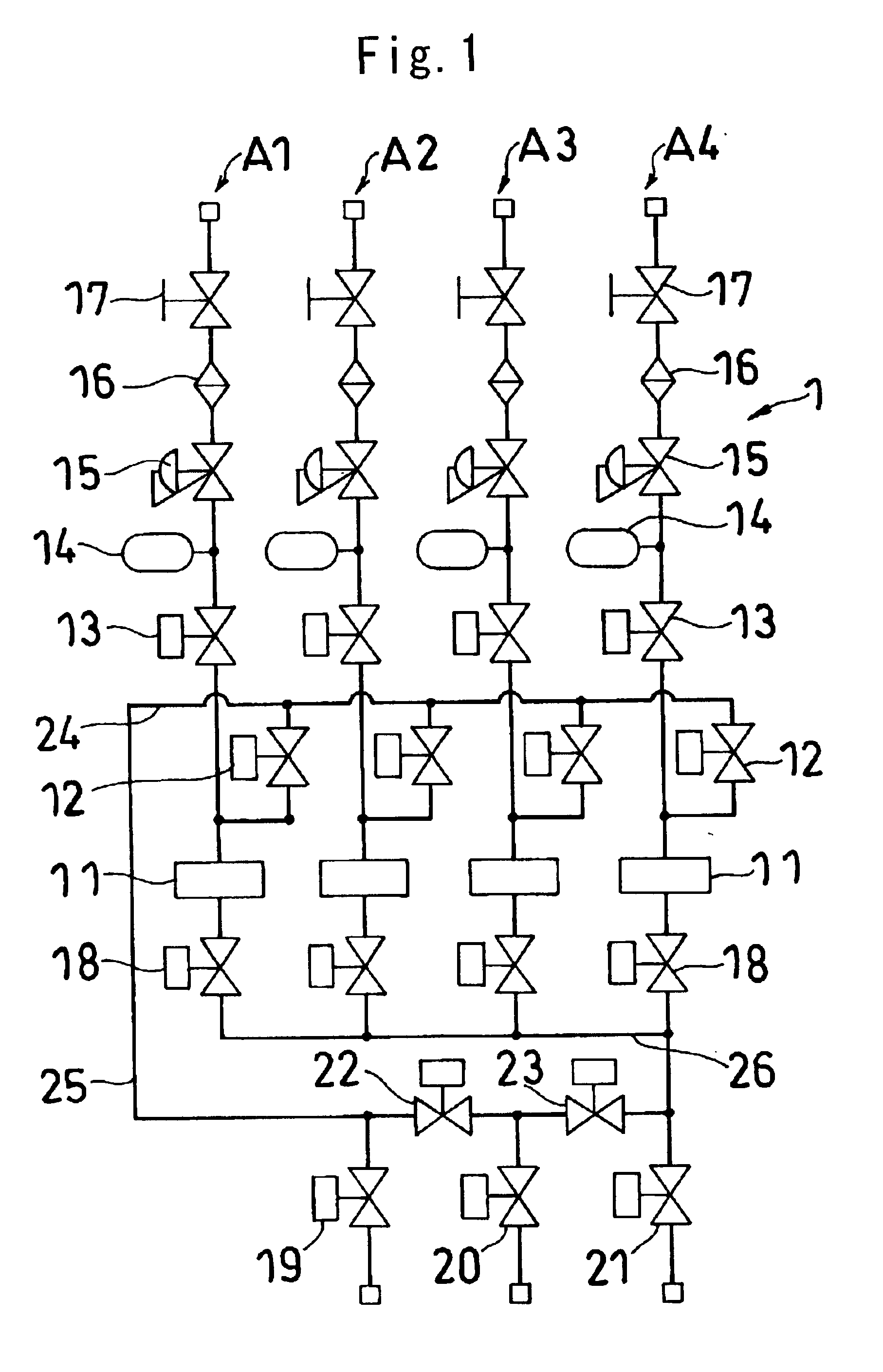
FIG. 1 is a piping diagram (in common for conventional fluid control apparatus) corresponding to a fluid control apparatus of the invention. The fluid control apparatus 1 comprises four lines A1, A2, A3, A4 arranged in parallel.

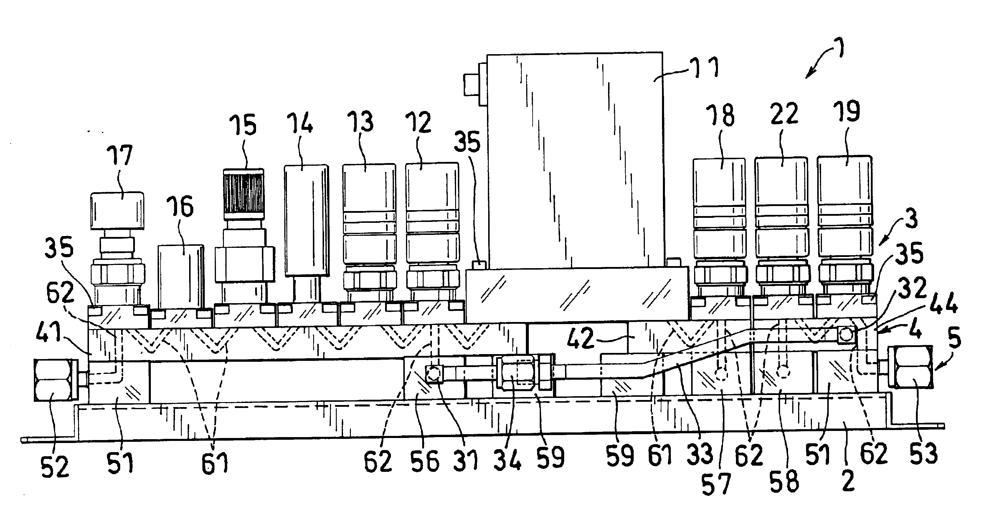
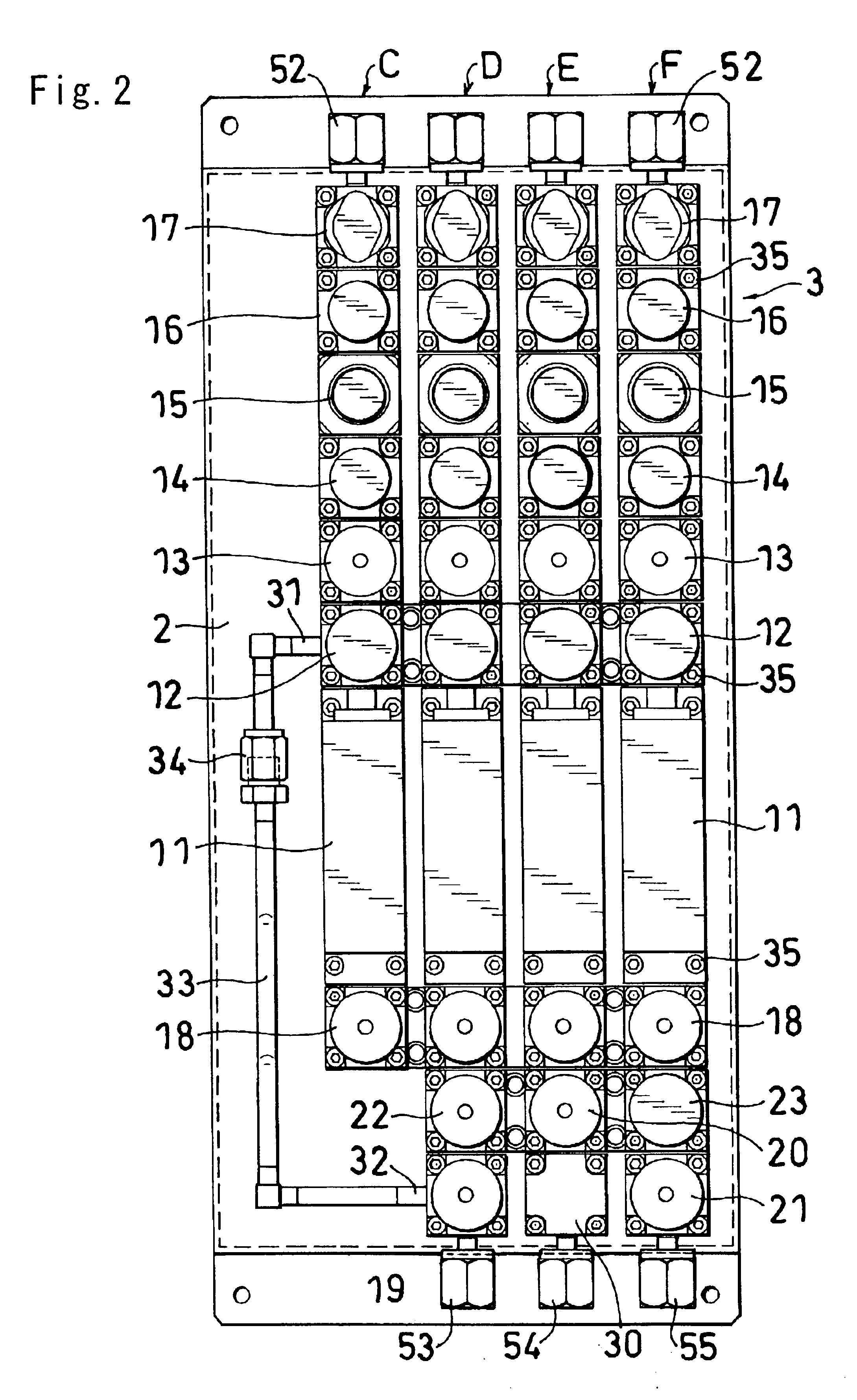
Each of the lines A1 to A4 is adapted to introduce a purge gas thereinto and comprises a massflow controller 11; an inlet-side first on-off value 12, inlet-side second on-off valve 13, pressure sensor 14, pressure regulator 15, filter 16 and inlet-side third on-off valve 17 which are arranged at the inlet side of the massflow controller 11; and an outlet-side on-off valve 18 disposed at the outlet side of the massflow controller 11. The lines A1 to A4 are provided at their outlet side with a purge gas inlet on-off valve 19, purge gas outlet on-off valve 20 and process gas outlet on-off valve 21 which are in common for these lines. A purge gas inlet / outlet changeover ...


PUM


Abstract

A connecting layer for interconnecting fluid control devices in series and in parallel comprises an upper connecting layer 4 and a lower connecting layer 5. The upper connecting layer 4 is provided by parallel rows each comprising block couplings 41, 42, 43, 44 arranged longitudinally of the apparatus, each of the block couplings having a longitudinal channel 61 for interconnecting the adjacent fluid control devices in the row and a through channel 62 communicating with the fluid control device. The lower connecting layer 5 is provided by block coupling 56, 57, 58 each having a lateral channel 64 for interconnecting the through channels 62 of the block couplings 41, 42, 43, 44 of the upper connecting layer 4 which are arranged laterally and by block couplings 51 each adapted to cause the through channel 62 of the block coupling 41, 43, 44 of the upper connecting layer 4 to communicate with an inlet-side or outlet-side coupling 52, 53. The couplings 51, 56, 57, 58 of the lower connecting layer 5 are attached to a base plate 2 with screws from above, and the couplings 41, 42, 43, 44 of the upper connecting layer 4 are attached to the couplings 51, 56, 57, 58 of the lower connecting layer 5 with screws form above.

Description

BACKGROUND OF THE INVENTIONThe present invention relates to fluid control apparatus for use in semiconductor manufacturing equipment, and more particularly to integrated fluid control apparatus which are so assembled that fluid control devices, such as massflow controllers and on-off valves, are connected by block couplings so as to be removable individually singly upward for inspection and maintenance.The terms “upper” and “lower” as used herein refer respectively to the upper and lower sides of FIG. 3, while these terms are used for the sake of convenience. The fluid control apparatus may be installed on a horizontal surface in the state shown in FIG. 3 or as turned upside down, or on a vertical surface.Integrated fluid control apparatus of the type mentioned and already known comprise a plurality of lines each comprising a plurality of fluid control devices, and connecting means provided under these lines for connecting the components of each line and interconnecting the lines. T...

Claims


Application Information

Patent Timeline
Patent Type & Authority Patents(United States)
IPC IPC(8): F16K27/00F16K51/02H01L21/00F17D1/02
CPCF16K51/02F16K27/003Y10T137/87885H01L21/00
Inventor YAMAJI, MICHIOTSUBOTA, KENJIHOSHIYAMA, HIDENAGA
Owner FUJIKIN INC
Why Eureka
Try Eureka