Switching device for multifunctional hand-held machine tool

a multi-functional, tool machine technology, applied in the direction of portable percussive tools, bulkheads/piles, large fixed members, etc., can solve the problems of unmotivated switching-off of combination hammers, unavoidable sudden rotational movement of tool machines,

Inactive Publication Date: 2005-03-22
HILTI AG
View PDF10 Cites 67 Cited by
  • Summary
  • Abstract
  • Description
  • Claims
  • Application Information

AI Technical Summary

Benefits of technology

It is therefore an object of the invention to provide a device for multifunctional hand-held tool machines, by which, when changing a mode of operation, for example, from a drilling to a chiseling operation in a combination hammer, information that ensures that certain electrical system functions are selected in conformity with the operating mode selected, is supplied to the electronics of the machine.

Problems solved by technology

In particular, an unmotivated switching-off of the combination hammer is undesirable since it would unnecessarily slow down the working process.
This is particularly true for certain application cases and courses, for which a sudden rotational movement of the tool machine is unavoidable, for example, when dressing the edges and borders of concrete constructions and when breaching walls with a chisel and the like.

Method used


Image

  • Switching device for multifunctional hand-held machine tool
  • Switching device for multifunctional hand-held machine tool
  • Switching device for multifunctional hand-held machine tool

Examples


first embodiment

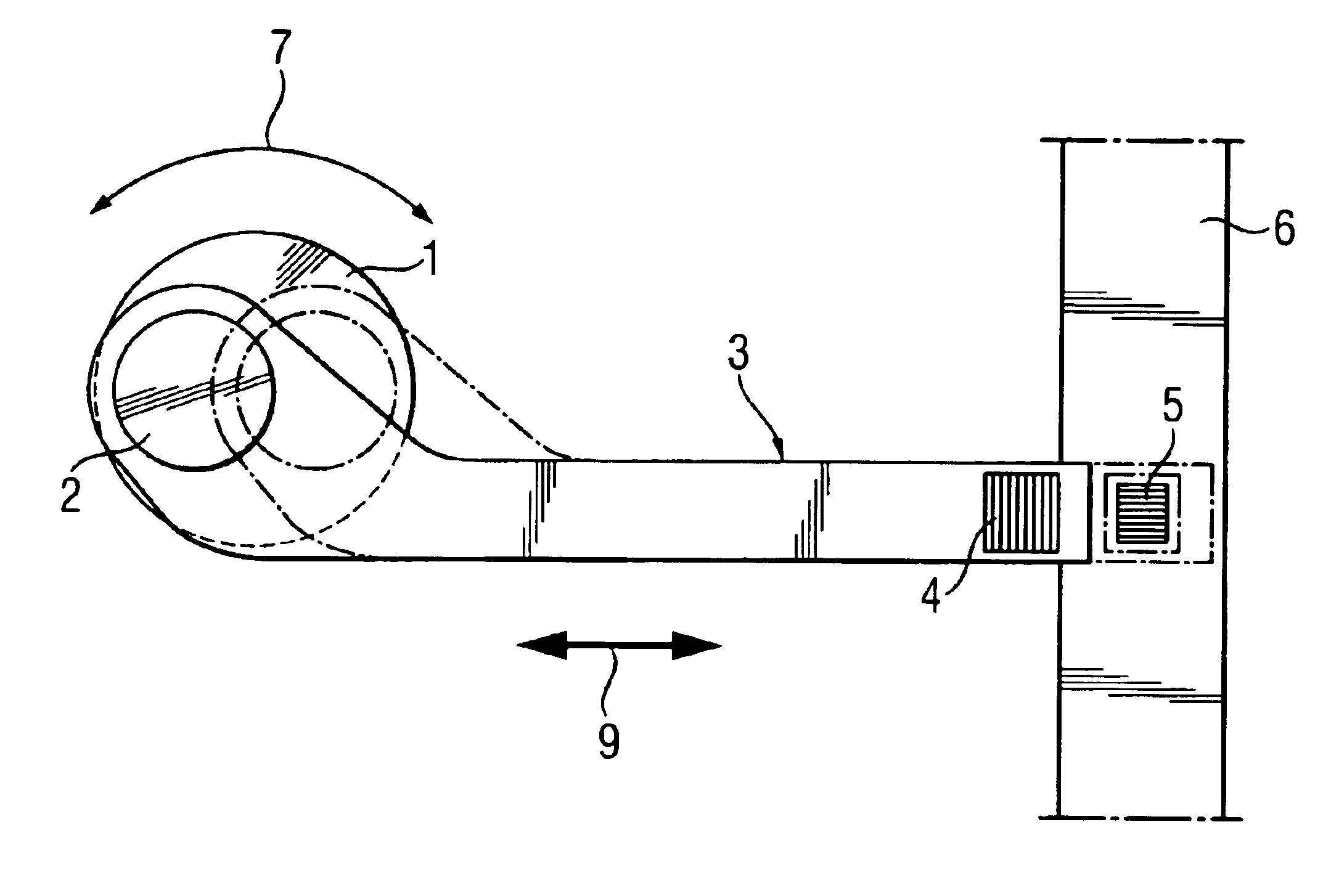
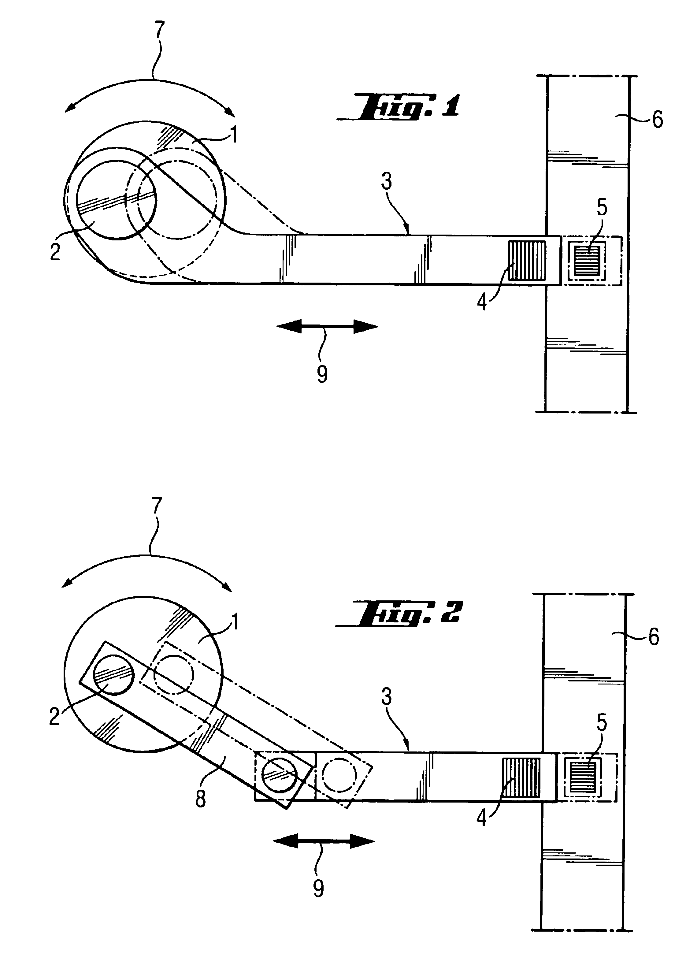
FIG. 1 illustrates a switching-off or changing-over device of the invention. In the housing (not shown) of an electrical combination hammer, there is a changeover knob 1, which can be adjusted between two positions, which are offset from one another usually by 180°, in the directions of a double arrow 7. In a combination hammer, it is possible to choose between the “chiseling” operating mode and the “hammer drilling” operating mode. The changeover knob 1 is provided on the inside of the tool machine, facing the viewer, with an eccentric crank pin 2. Crank pin 2, is, preferably, integrally molded in one piece and a switch rod 3, which can be shifted back and forth in the form of a connecting rod, is rotatably mounted on pin 2 and, when the “hammer drilling” switching position is selected, is in the position shown by the solid lines. On the other hand, if the user selects the “chiseling” mode of operation, the switch rod 3 is shifted to the right in the direction of arrow 9, as shown ...

second embodiment

the invention is illustrated in FIG. 2, wherein there is a different construction of the back and forth crank driving mechanism of the connecting rod 3 from the one illustrated in FIG. 1. Depending on the spatial relationships of the machine, this embodiment of the invention, for which the connecting rod 3 is driven over a crank 8, may be preferred.

third embodiment

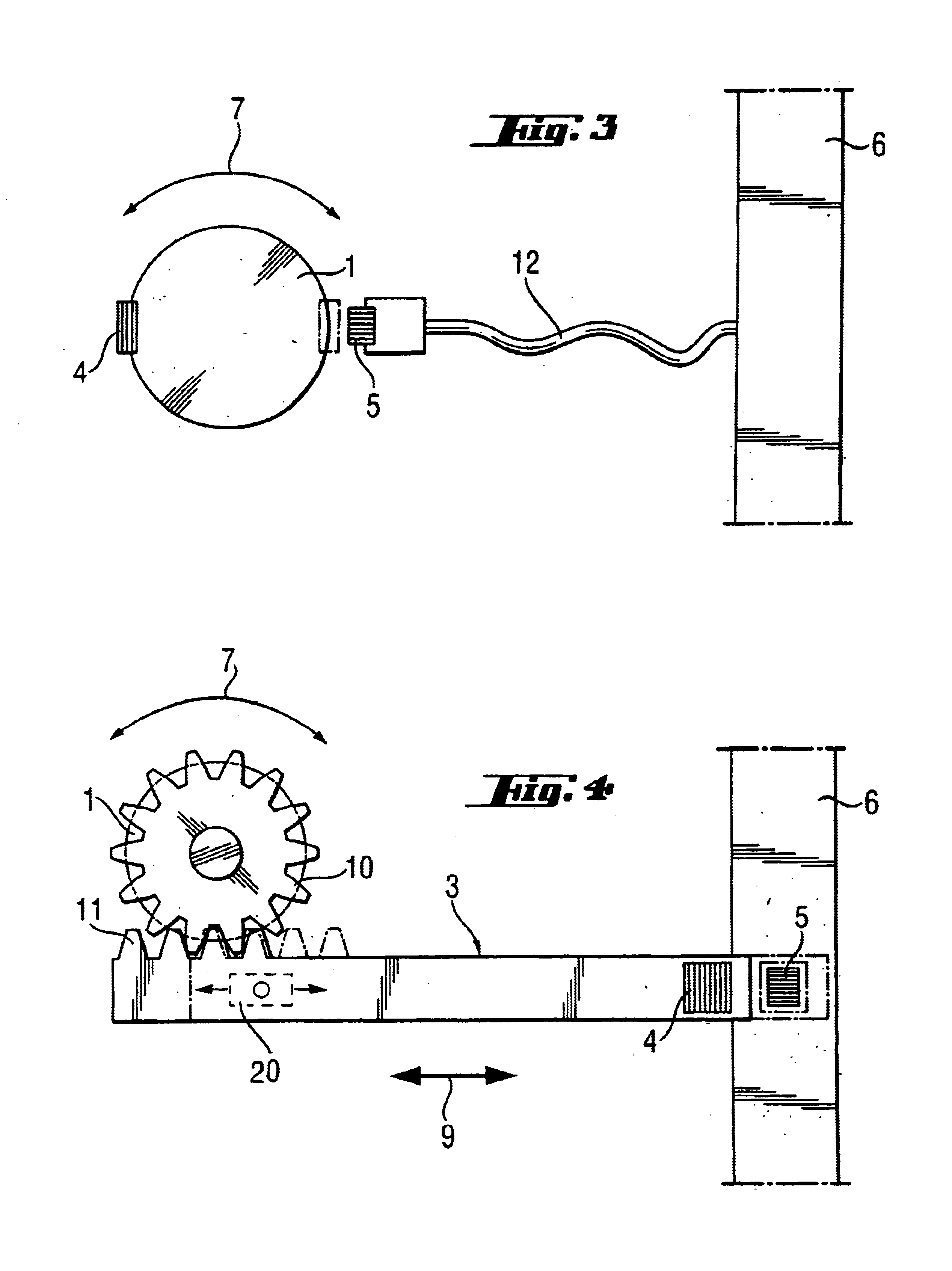
In the invention, as illustrated in FIG. 3, the permanent magnet 4 is fastened to the interior of the machine directly at the switch 1. The Hall sensor 5 is led over a cable connection 12 out of the driving and monitoring electronics 6 into the immediate vicinity of the knob 1. In the “hammer drilling” position, the permanent magnet 4, again, is remote from the Hall sensor 5; the reaction moment monitoring system is active. If the “chiseling” position is selected, the reaction moment monitoring system is inactive; at the same time, certain other operating parameters are specified.

In the forth embodiment of the invention, as illustrates in FIG. 4, the switch rod 3 has at least at the end, facing the knob 1, a partial denticulation 11, which meshes with a gear wheel 10, which is disposed on the inside of the machine and is seated on the axis of the knob 1. With this driving mechanism for the changeover device, a safe and reliable movement and positioning of the switching magnet 4, in ...


PUM

PropertyMeasurementUnit
electrical functionsaaaaaaaaaa
relative angle of rotationaaaaaaaaaa
angle of rotationaaaaaaaaaa

Abstract

The object of the invention is a device, intended for a multifunctional, hand-held tool machine, for example, an electric combination hammer, for the ON/OFF switching or changeover of individual system functions when changing the processing mode, for example, from “hammer drilling” to “chiseling”. Pursuant to the invention, the changeover device, which is to be actuated by the user, is coupled with a mechanical driving mechanism, by which a bistable switch, comprising two mutually oppositely movable elements, is actuated. In a combination hammer, the invention guarantees that, when the chiseling operation is selected, certain functions of the system, such as a monitoring of the reaction moment, are interrupted or changed over.

Description

FIELD OF INVENTIONThe invention relates to a device in a multifunctional hand-held tool machine for the ON / OFF or changeover switching of individual electrical functions of a system when the user changes the processing mode by actuating a switching device present on the machine.BACKGROUND INFORMATION AND PRIOR ARTMultifunctional, hand-held tool machines include, but are not limited to, for example, circular saws, orbital sanders, vibrating grinders, drills or impact drills, as well as combination hammers, which are converted over from a drilling to a chiseling operation. It is understood that the latter type of equipment is an example and is not meant to limit the universal applicability of the invention described herein.In combination hammers, when the drilling operation is selected, a tool and its holding head are driven to rotate with or without impacting. On the other hand, when the chiseling operation is selected, the tool, that is, the chisel is driven exclusively forwards and...

Claims


Application Information

Patent Timeline
Patent Type & Authority Patents(United States)
IPC IPC(8): B25D16/00B25F5/00B23B45/16B23Q1/00H01H15/02H01H19/635H01H35/00H01H36/00
CPCB25D16/006B25D2250/221B25D2250/255B23Q1/00
Inventor MANSCHITZ, ERWINHELLMANN, PETER
Owner HILTI AG
Why Eureka
Try Eureka