Jack

a technology of jacks and contacts, applied in the direction of coupling devices, two-part coupling devices, electrical devices, etc., can solve the problems of difficult to realize favorable performance, the contact piece tip may end up in plastic deformation, and the difficulty in designing a structure in which elastic spring force is attained when used for long time, etc., to achieve the effect of holding reliably

Inactive Publication Date: 2005-03-22
HOSIDEN CORP
View PDF3 Cites 29 Cited by
  • Summary
  • Abstract
  • Description
  • Claims
  • Application Information

AI Technical Summary

Benefits of technology

That is to say, with this configuration, it is possible to connect two ring electrodes and a tip electrode, such as in a stereo plug. Moreover, a pair of intermediate contacts are arranged at positions clamping the ring electrode on the base end side of the plug, so that when the plug is inserted into the plug insertion hole, the pair of intermediate contacts clamps the plug, and the plug's orientation is stabilized, while keeping the plug from coming out off the jack. As a result, a jack is achieved with which an inserted plug can be held reliably.

Problems solved by technology

However, if slackening or loosening occurs at the site at which the connection terminal is supported by the jack unit, then an adequate contact force may not be attained, which may lead to a bad contact, thus leaving room for improvement.
In these kinds of jacks, even though there is a need for forming the tip contact piece in a compact manner, in view of keeping the overall jack from becoming bigger, the tip contact piece is arranged at an end location of the jack, so that it is difficult to design a structure in which an elastic spring force is attained when used for long spans of time, thus leaving room for improvement.
In particular, with a tip contact piece that is made small, as in the latter of the pieces of related art, when the tip contact piece is deformed greatly, such as when a large prying force is applied from the plug, the tip contact piece may be ultimately enter a state of plastic deformation, so that a favorable performance was difficult to realize.

Method used


Image

  • Jack
  • Jack
  • Jack

Examples


Embodiment Construction

Referring to the accompanying drawings, the following is an explanation of embodiments of the present invention.

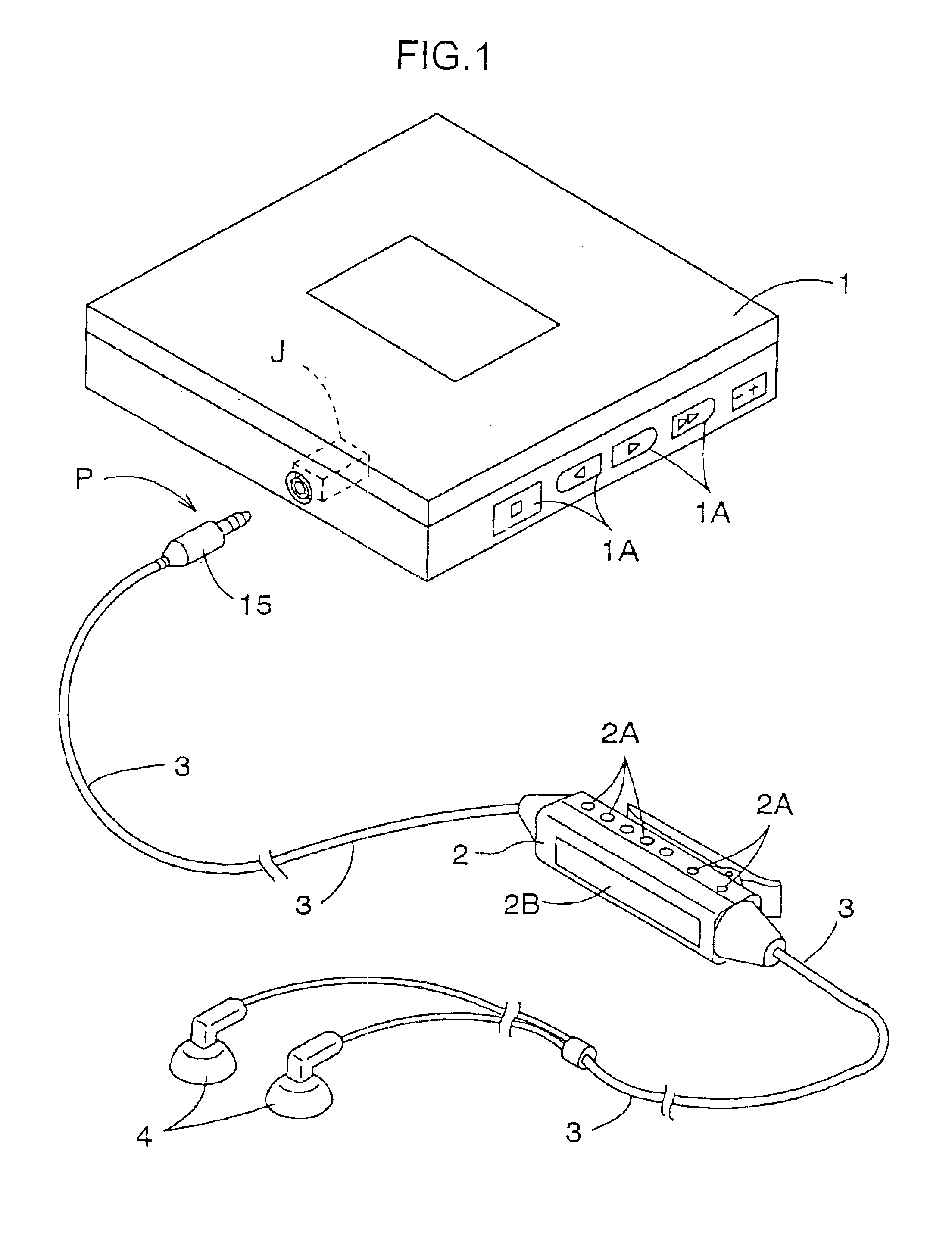
A jack J in accordance with the present invention can be provided in a mobile phone or, as shown in FIG. 1, in a portable audio device 1, such as an MD player or a CD player. As shown in FIG. 1, the jack J is configured so as to allow use of a single-prong plug P for connecting stereo ear-phones 4 or headphones (not shown in the drawings) via a cable 3 that is provided with a controller 2 at an intermediate portion.

As shown in FIG. 1, when using the plug P having the controller 2, it is possible to play or stop the audio saved on a medium placed in the audio device 1 or to control the volume or the like by operating a plurality of switches 2A provided on the controller 2. If the controller 2 is provided with a liquid crystal display 2B as shown in FIG. 1, then its control state can be displayed. The jack J can also be used for an ordinary plug P that is not provided with a...


PUM


Abstract

In order to configure a jack (J) that realizes a favorable conductive state by bringing a tip electrode (10) at a front end of a plug (P) into reliable contact with a contact without making the jack bigger, a contact unit (CU) having a pair of tip contacts (CT) that contact the tip electrode (10) at the front end of the plug (P) in an embracing fashion is incorporated in a body (20). The contact unit (CU) is made of a linking portion (23), intermediate portions (24) that extend from both ends of the linking portion (23) towards an aperture side of the plug insertion hole (H), and folded portions (25) that are folded over from the ends of the intermediate portions (24) to the inner end side of the plug insertion hole (H), projecting into the plug insertion hole (H), the contact unit being formed in one piece by bending a band-shaped conductor, such as a copper alloy, and the tip contacts (CT) being formed on a free end side of the folded portions (25).

Description

BACKGROUND OF THE INVENTION1. Field of the InventionThe present invention relates to jacks that are provided with a plurality of contacts along a plug insertion hole formed in a body, the contacts including tip contacts that contact a tip electrode at a front end of a plug that is inserted onto the plug insertion hole, and intermediate contacts that contact a ring electrode at an intermediate location of the plug.2. Description of the Related ArtConventionally, the jacks disclosed in Japanese Patent No. 2633258 and Japanese Patent Application Publication No. JP 2001-217053A are known as jacks similar to the one disclosed in the present invention. Among these pieces of related art, the former is configured such that when a multipolar plug is inserted into a jack unit (corresponding to the body in the present invention), a conductive state is established by bringing a plurality of connection plug contacts (a concept including the tip electrode and the ring electrodes of the present in...

Claims


Application Information

Patent Timeline
Patent Type & Authority Patents(United States)
IPC IPC(8): H01R24/04H01R24/00H01R24/02
CPCH01R24/40H01R24/58H01R12/57H01R2107/00H01R2103/00
Inventor NAKAI, YUJIMATSUMOTO, KOJI
Owner HOSIDEN CORP
Why Eureka
Try Eureka