
Electronic battery tester with network communication

a technology of electronic battery tester and network communication, applied in the field of electronic battery tester, can solve the problems of largely unrecognized benefits of increasing the amount of data

Inactive Publication Date: 2005-03-22
MIDTRONICS
View PDF300 Cites 159 Cited by
  • Summary
  • Abstract
  • Description
  • Claims
  • Application Information

AI Technical Summary

Problems solved by technology

However, advantages from this increased amount of data has been largely unrecognized.

Method used


Image

  • Electronic battery tester with network communication
  • Electronic battery tester with network communication
  • Electronic battery tester with network communication

Examples


Embodiment Construction

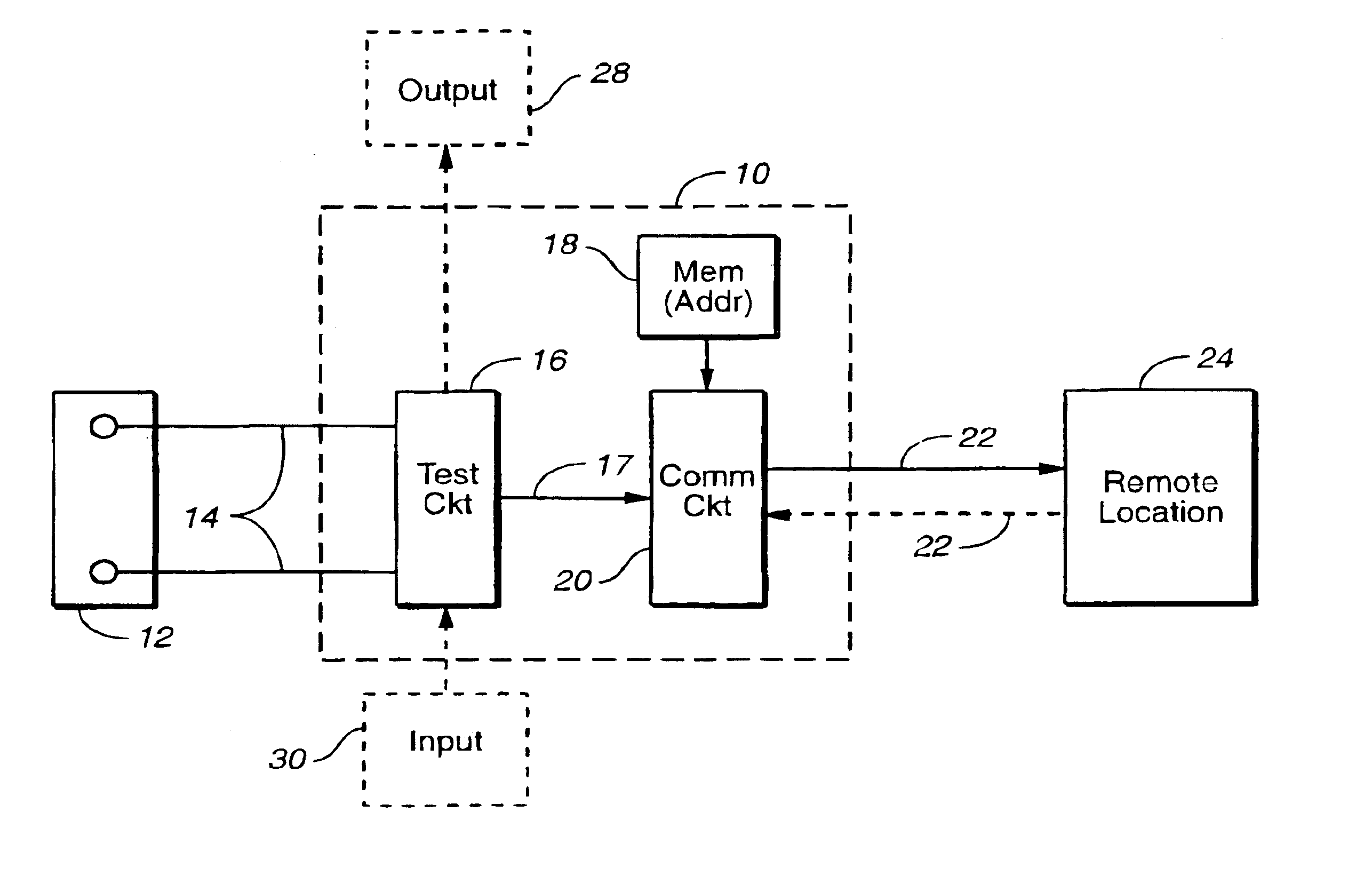
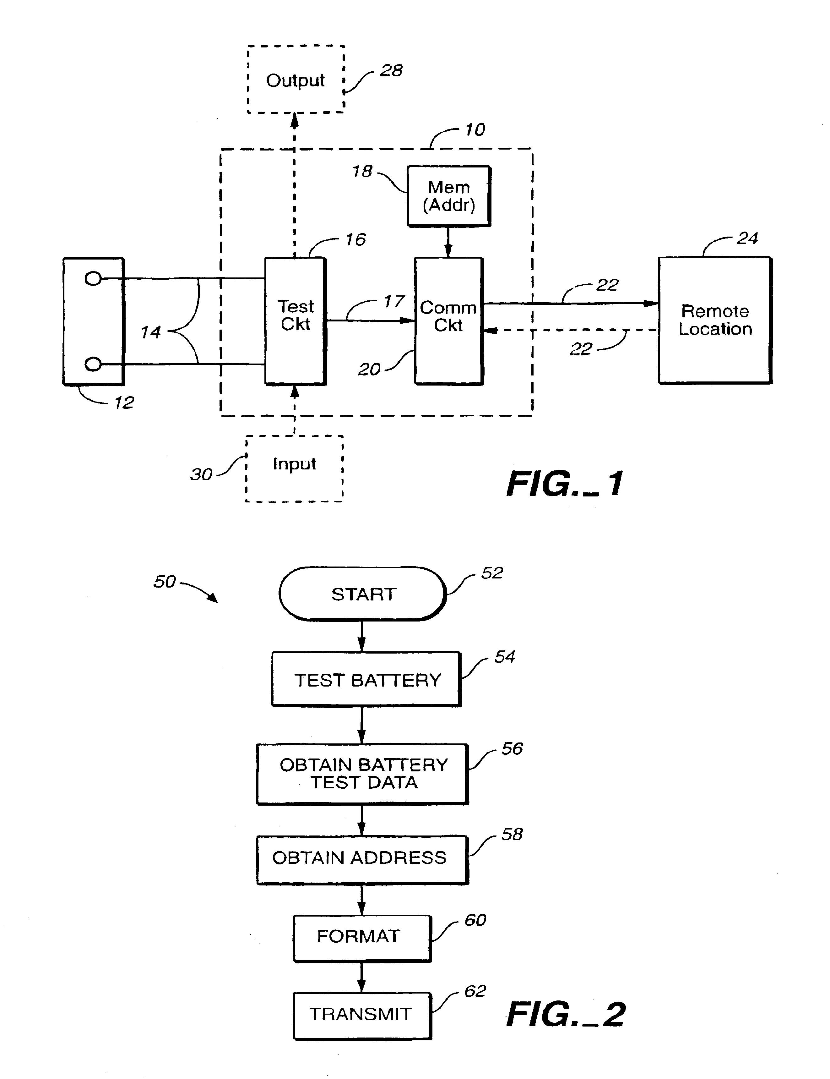
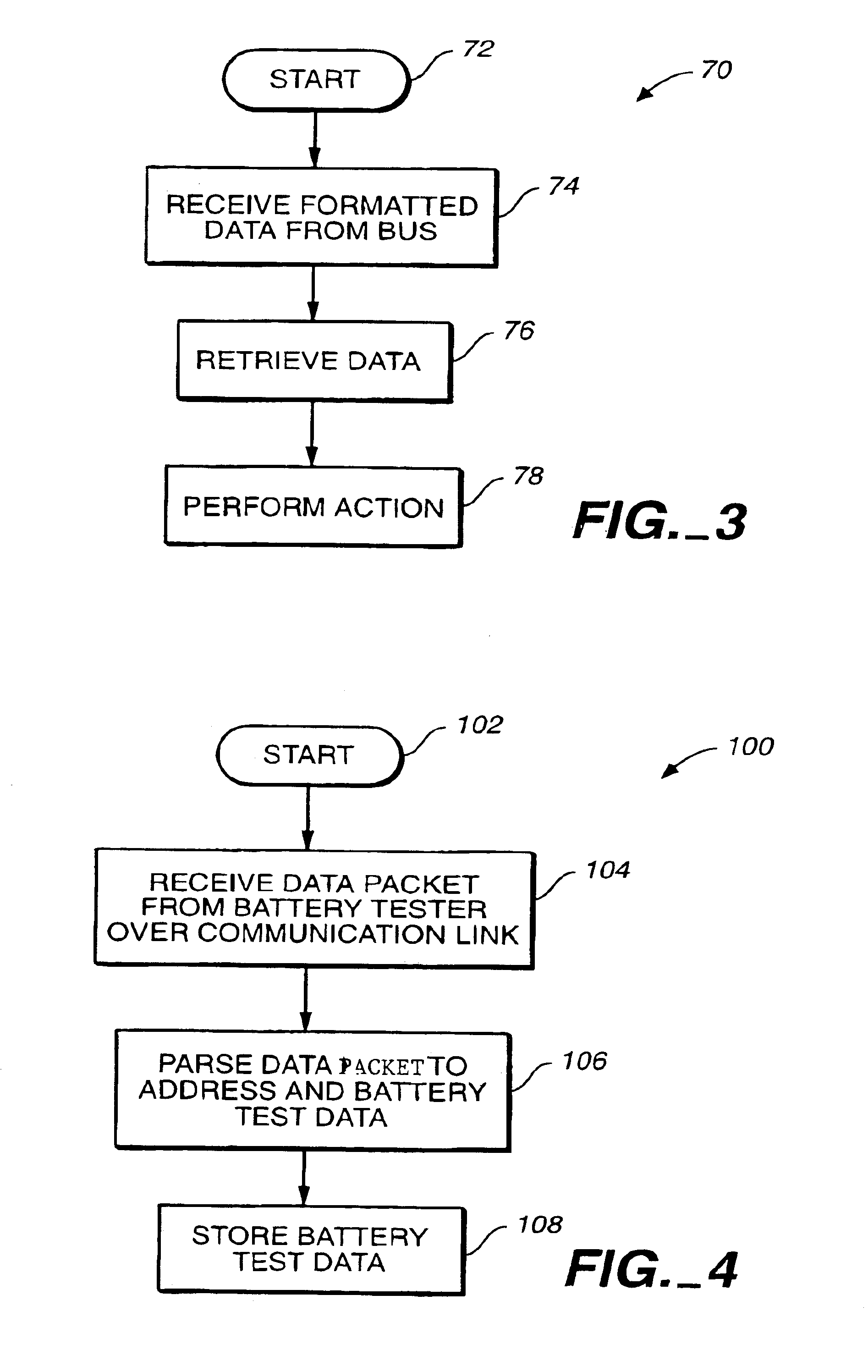
The present invention includes the recognition that the output from electronic battery testers can provide useful diagnostic or other information for analysis to a remote location. In one aspect, the present invention includes providing an electronic battery tester with a battery tester address and transmitting the result of a battery test, data recovered the test during or from the battery, or related to the battery test, to a remote location in a manner in which the battery tester address is formatted (i.e., in some way combined or associated with) with the battery test data. This information is transmitted to a remote location for subsequent review or processing. Similarly, the battery tester can receive information when the information is associated with the battery tester address.

FIG. 1 is a simplified block diagram showing an electronic battery tester 10 in accordance with one example embodiment of the present invention. Electronic battery tester 10 couples to storage battery ...


PUM


Abstract

An electronic battery tester for testing a storage battery includes test circuitry configured to provide a battery test output related to a condition of the battery. A memory stores a battery tester address of the battery tester, and communication circuitry transmits the battery test output formatted with the battery tester address on a communication link to a remote location.

Description

BACKGROUND OF THE INVENTIONThe present invention relates to electronic battery testers of the type used to perform tests on storage batteries.Electronic battery testers are used to test and determine the condition of storage batteries. Examples of electronic battery testers and related technologies are shown in U.S. Pat. No. 3,873,911, issued Mar. 25, 1975, to Champlin, entitled ELECTRONIC BATTERY TESTING DEVICE; U.S. Pat. No. 3,909,708, issued Sep. 30, 1975, to Champlin, entitled ELECTRONIC BATTERY TESTING DEVICE; U.S. Pat. No. 4,816,768, issued Mar. 28, 1989, to Champlin, entitled ELECTRONIC BATTERY TESTING DEVICE; U.S. Pat. No. 4,825,170, issued Apr. 25, 1989, to Champlin, entitled ELECTRONIC BATTERY TESTING DEVICE WITH AUTOMATIC VOLTAGE SCALING; U.S. Pat. No. 4,881,038, issued Nov. 14, 1989, to Champlin, entitled ELECTRONIC BATTERY TESTING DEVICE WITH AUTOMATIC VOLTAGE SCALING TO DETERMINE DYNAMIC CONDUCTANCE; U.S. Pat. No. 4,912,416, issued Mar. 27, 1990, to Champlin, entitled ...

Claims


Application Information

Patent Timeline
Patent Type & Authority Patents(United States)
IPC IPC(8): G01R31/36H02J7/16H02J7/00G01R31/00
CPCG01R31/3627H02J7/163H02J7/0004H02J7/0008H02J7/008G01R31/3648G01R31/007G01R31/3631G01R31/385G01R31/386H02J7/00041H02J7/00036H02J7/00047H02J7/0047
Inventor BERTNESS, KEVIN I.
Owner MIDTRONICS
Learn More