Cap opening system and method for opening cap

a technology of which is applied in the field of cap opening system and opening method for opening cap, can solve the problems of inability to carry out cap opening operation for containers having various container bodies and caps, large apparatus structure, and inability to meet the needs of use, and achieve the effect of reliably carrying out the operation of the cap opening operation

Inactive Publication Date: 2005-03-29
HITACHI LTD +1
View PDF9 Cites 35 Cited by
  • Summary
  • Abstract
  • Description
  • Claims
  • Application Information

AI Technical Summary

Benefits of technology

The present invention is made in view of the problem in the prior art described above. Therefore, an object of the present invention is to provide a cap opening system which can perform a cap opening operation reliably.
In this case, the polygonal member may be a triangle member provided horizontally, wherein the rotation of the triangle member can be prevented (stopped) when two of three edges of the triangle member are abutted to two abutment members. Of course, as for the preventing means, other various means can be adopted so long as the rotation of the rotary unit is prevented when releasing the cap.

Problems solved by technology

Various cap opening apparatuses have been proposed in the prior art, but any apparatus that can be applied to various types of containers and caps has not yet been put to practical use.
Accordingly, when the operation conditions of the apparatus are fixed or standardized, it is difficult to carry out a cap opening operation for containers having various container bodies and caps.
Further, when one mechanism is provided to grasp the cap and a separate mechanism is provided to rotate the grasped cap, the structure of the apparatus necessarily becomes large and complex.
Furthermore, in the case where caps having various diameters are to be handled, it is desirous that a predetermined grasping force is applied irrespective of the cap diameter and that the cap is rotated at high speed from the point in time when such predetermined grasping force is created, but mechanisms in response to such demand have not yet been realized up to now.

Method used


Image

  • Cap opening system and method for opening cap
  • Cap opening system and method for opening cap
  • Cap opening system and method for opening cap

Examples


Embodiment Construction

The preferred embodiments of the present invention will be described below with reference to the drawings.

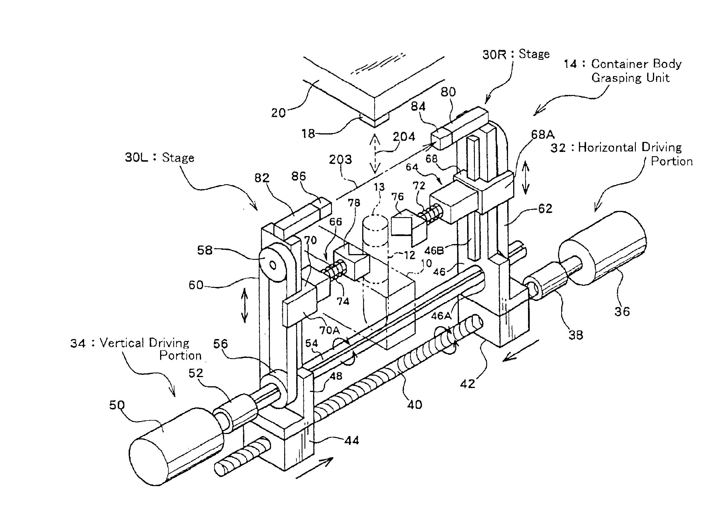
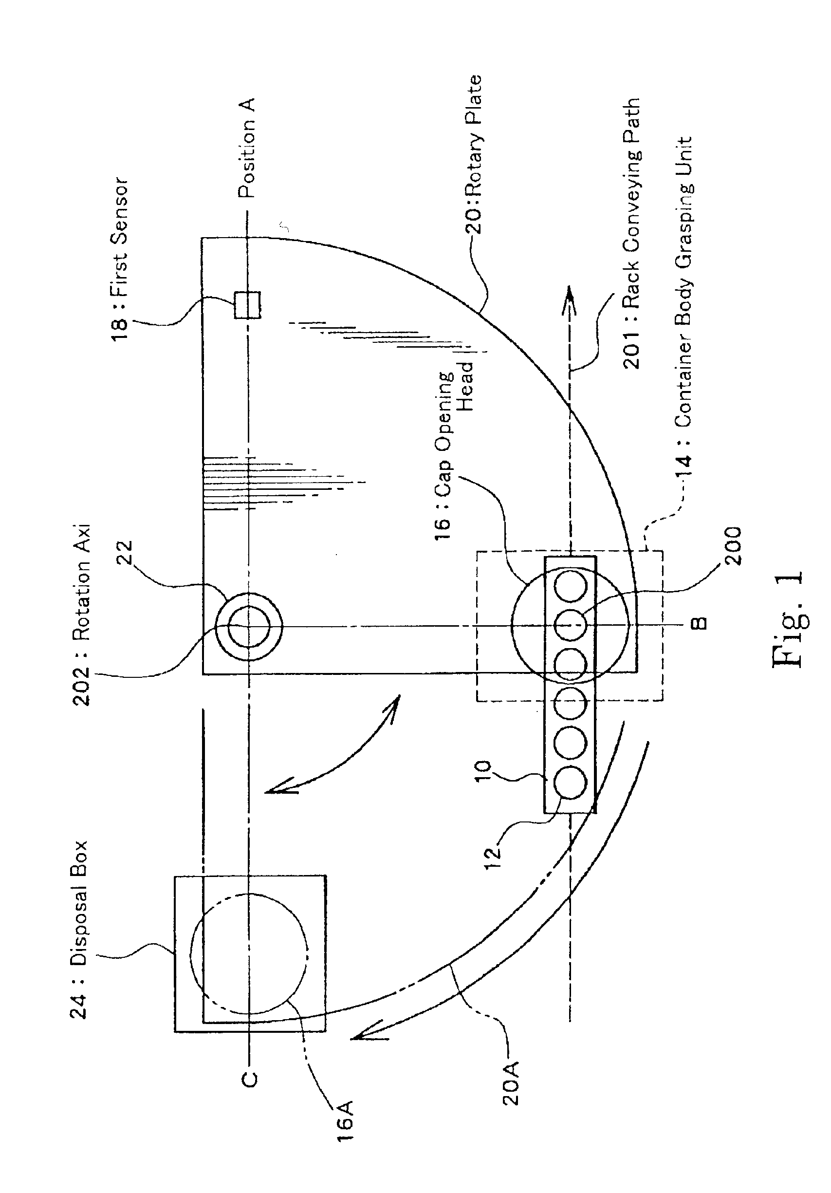
FIG. 1 is a top schematic view of the structure of a cap opening system according to the present invention. This cap opening system removes the cap provided on the upper opening of a container body 12 such as a test tube or the like supported by a rack 10, and then discards such cap. In FIG. 1, the rack 10 is conveyed along a rack conveying path 201. The conveying of the rack 10 is carried out by a rack conveying mechanism (not shown in the drawing). The container body 12 provided with a cap to be opened is positioned at a cap opening position indicated by the reference numeral 200.

In the present embodiment, a fan-shaped rotary plate (which is a movable member as claimed) 20 is provided above the rack 10. The rotary plate 20 rotates 90 degrees about a rotation axis 22. The rotation of the rotary plate 20 is carried out by a rotary plate driving section not shown in the drawing. ...


PUM


Abstract

A cap opening system which can handle various containers having caps and container bodies of different sizes is disclosed. In this system, when a cap of a container is to be opened, a container body of the container is gripped by a container body holding apparatus to raise the container body upward. A top surface of the cap is detected as a reference surface when the cap interrupts an optical beam. Based on the height of the reference surface, the cap is positioned with respect to the cap handling apparatus. Alternatively, a cap receiving member is provided underneath the cap handling apparatus to perform positioning of the cap with respect to the cap handling apparatus.

Description

BACKGROUND OF THE INVENTION1. Field of the InventionThe present invention is related to a cap opening system and a method for opening a cap, and in particular is related to a system and method for removing a cap provided in the upper portion of a container body of a container.2. Description of the Prior ArtA cap opening apparatus used in a sample preprocessing system or the like is an apparatus which automatically removes a cap provided in a container such as a test tube or the like. Various cap opening apparatuses have been proposed in the prior art, but any apparatus that can be applied to various types of containers and caps has not yet been put to practical use. Namely, there are a wide variety of container body shapes (lengths in particular) and cap sizes (thicknesses in particular) depending on the type of container. Accordingly, when the operation conditions of the apparatus are fixed or standardized, it is difficult to carry out a cap opening operation for containers having ...

Claims


Application Information

Patent Timeline
Patent Type & Authority Patents(United States)
IPC IPC(8): B67B7/00B67B7/02B67B7/18
CPCB67B7/182B67B7/02
Inventor NIWAYAMA, HIROAKIIDA, YASUMICHIKOJO, YOSHIYUKIMIYAZAKI, KENICHITAKIZAWA, HIROYUKI
Owner HITACHI LTD
Why Eureka
Try Eureka