Flow control valve with automatic shutoff capability

a flow control valve and automatic shutoff technology, applied in the direction of valve operating means/release devices, valve couplings, mechanical equipment, etc., can solve the problems of manual shutoff valves that are difficult to turn, simple repair of flow control valves that may take a large amount of time and effort, and the on time of the valve may be altered

Inactive Publication Date: 2005-03-29
ARICHELL TECH INC
View PDF16 Cites 35 Cited by
  • Summary
  • Abstract
  • Description
  • Claims
  • Application Information

AI Technical Summary

Benefits of technology

Also, the housing contains a check valve in the fluid path between the inlet and that valve assembly. Normally, that check valve is maintained in an open condition by the valve assembly. However, when the retaining means are loosened to remove the valve assembly from the housing, the check valve automatically closes thereby stopping the flow of water from the inlet to the interior of the housing beyond the check valve. Therefore, when it becomes necessary to repair or replace any part of the valve assembly, the entire valve assembly can be removed from the housing without having to stop the flow of water to the flow control valve, i.e., without having to locate and turn off a manual shut off valve in the water feed line to the flow control valve.
Another feature of the present valve, to be described in detail later, is its ability to be coupled to feed or drain lines approaching in the valve from various directions thus avoiding the need to stock valves with different handedness.

Problems solved by technology

In the case of the valves whose on-time is controlled hydraulically by water flow through small orifices or passages in the valves, dirt and minerals can accumulate those passages, thereby altering the on time of the valve and necessitating a cleaning of those passages.
In some cases, that manual shut off valve may be difficult to turn because it has not been used for a long period of time.
Resultantly, a simple repair of a flow control valve may take an excessive amount of time and effort because of the necessity to turn off the water flow to the valve.

Method used


Image

  • Flow control valve with automatic shutoff capability
  • Flow control valve with automatic shutoff capability

Examples


Embodiment Construction

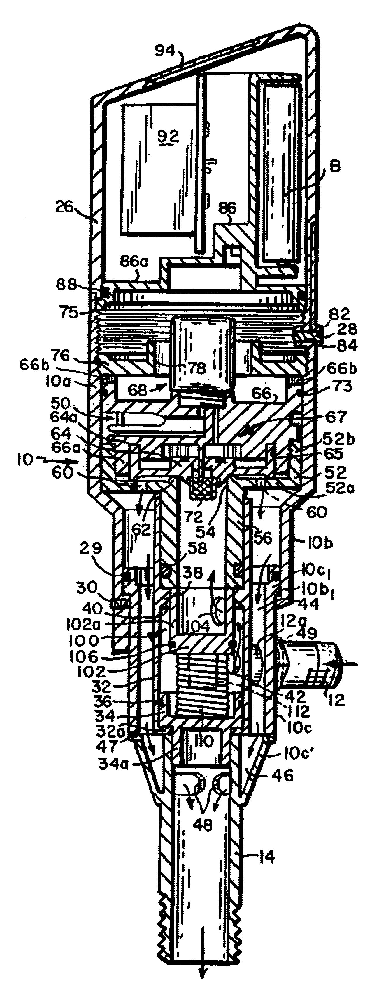
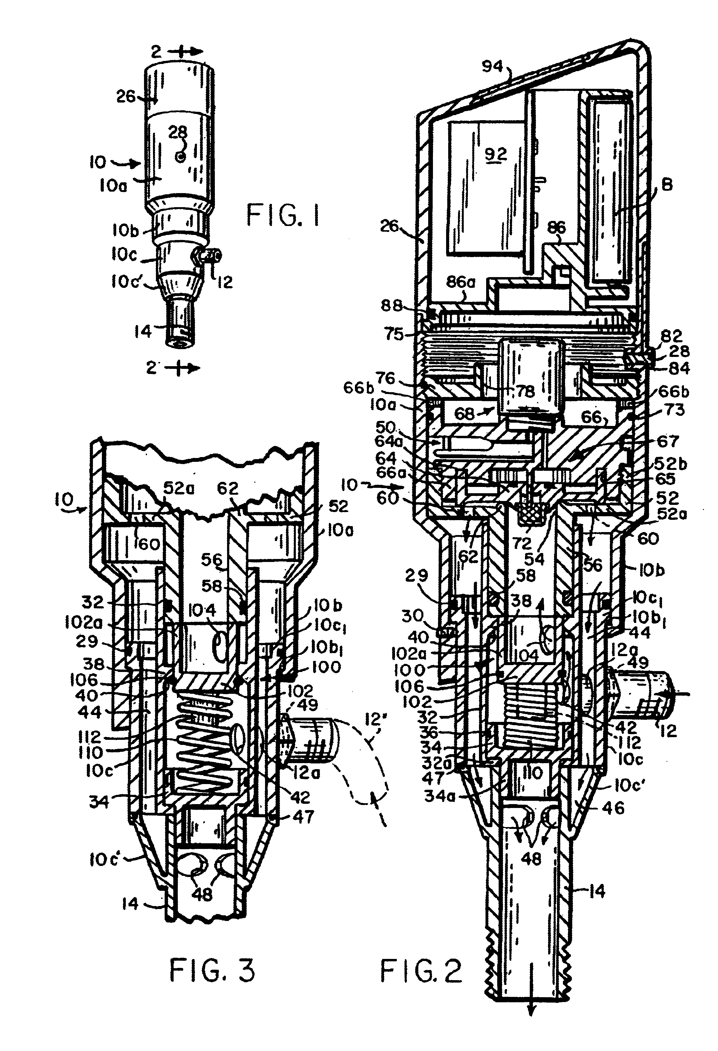
Referring to FIGS. 1 and 2 of the drawing, the valve comprises a housing shown generally at 10. The housing includes a relatively large diameter upper section 10a which necks down to a smaller diameter intermediate section 10b which leads, in turn, to a still smaller diameter section 10c. A valve inlet 12 extends into the interior of the housing through the side wall of section 10c and a valve outlet 14 extends from the lower end of the housing, the outlet being in fluid communication with the interiors of section 10c and a tapered extension 10c′ thereof. The upper end of housing section 10a is open and may be closed by a cap 26 releasably secured to section 10a by suitable fastening means such as a set screw 28. As we shall see, cap 26 contains the valve actuator and control electronics. When the valve is in use, the inlet 12 is connected to a water feed line (not shown) and the outlet 14 is connected to a fixture (not shown), such as a urinal or other device that requires flushing...


PUM


Abstract

A valve includes a housing having a fluid inlet and a fluid outlet and defining a fluid flow path between the inlet and the outlet. A check valve positioned in the housing has a valve seat in the flow path from the inlet, a valve member movable between a seated position against the valve seat blocking fluid flow from the inlet past the valve seat and an unseated position spaced away from the valve seat, and a spring for biasing the valve member toward the seated position. A main valve assembly is removably positioned at a home position in the housing in the flow path to control the fluid flow from the check valve to the outlet. The valve assembly has a portion which engages the valve member and maintains the valve member in it's unseated position so long as the main valve assembly is at the home position, the valve member being moved to the unseated position by the spring upon removal of the main valve assembly from the housing.

Description

BACKGROUND OF THE INVENTION1. Field of the InventionThis invention relates generally to flow control valves. It relates especially to a valve for controlling the flushing of urinals or toilets, although the invention also has application to other types of valves.2. Background InformationA typical flush control valve includes a housing with an inlet, an outlet and a valve seat located in the flow path between the inlet and outlet. A valve member in the housing is movable toward and away from the valve seat to control the flow of water from the inlet to the outlet. The valve member is moved between these two positions by an actuator of some kind. The actuator may be a lever arm or button which is linked to the valve member mechanically and / or hydraulically. Alternatively, the actuator may be an electromechanical device such as a solenoid controlled by a proximity sensor which senses the presence of someone positioned close to the valve. In any event, the typical flush control valve is...

Claims


Application Information

Patent Timeline
Patent Type & Authority Patents(United States)
IPC IPC(8): E03D3/00E03D3/02F16K43/00
CPCF16K43/005E03D3/02
Inventor PARSONS, NATAN F.
Owner ARICHELL TECH INC
Why Eureka
Try Eureka