Sash lock

a sash lock and sash technology, applied in the direction of fastening means, mechanical devices, carpet fasteners, etc., can solve the problems of complex spring design, inoperable window, and inability to securely lock the sash or prevent the sash, and achieves convenient and cost-effective use, increased preload, and positive audible snap

Inactive Publication Date: 2005-03-29
HOWARD BERGER CO +1
View PDF7 Cites 60 Cited by
  • Summary
  • Abstract
  • Description
  • Claims
  • Application Information

AI Technical Summary

Benefits of technology

The sash lock in accordance with the present invention does not require a track to guide the slide in either direction, the slide being spring loaded and therefore automatically throwing the slide once the rotation of the lever is started. Also, the use of a retaining ring at the bottom of the slide controls the vertical movement of the slide, allowing a posi

Problems solved by technology

A problem with this device is that the two protruding guide rails into which the slide is snapped control the throw of the slide and can cause binding since the drive pin on the bottom of the cam that operates the slide is off center.
If the slide binds, the sash lock will not securely lock the sashes or prevent the sashes from being opened.
Also, since the slide is generally made of plastic material with no means of control of the vertical movement, and since the drive p

Method used


Image

  • Sash lock
  • Sash lock
  • Sash lock

Examples


Embodiment Construction

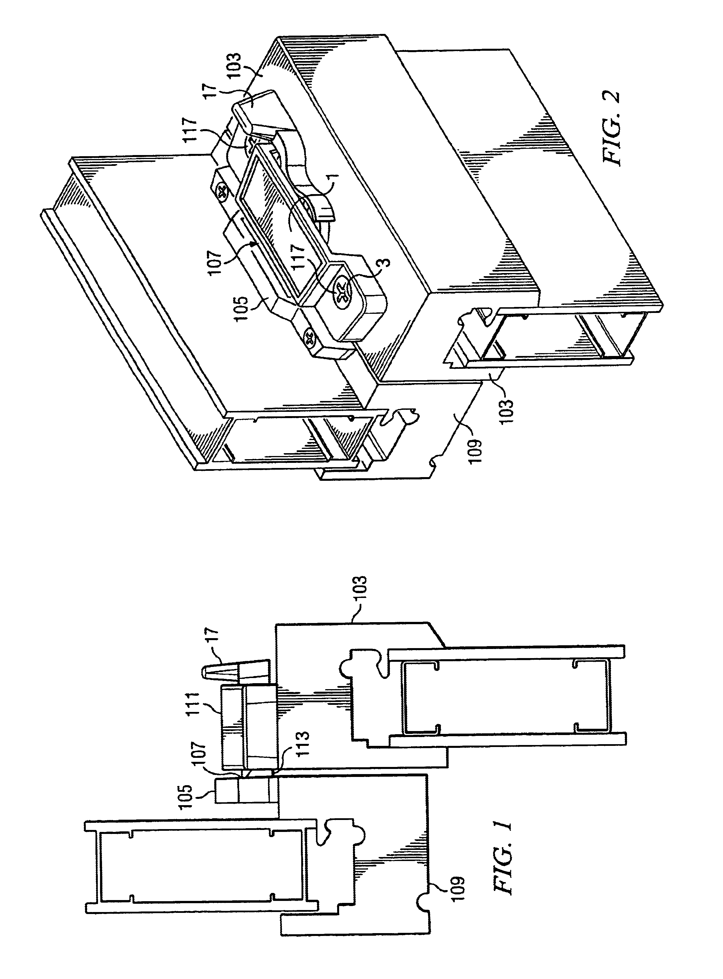
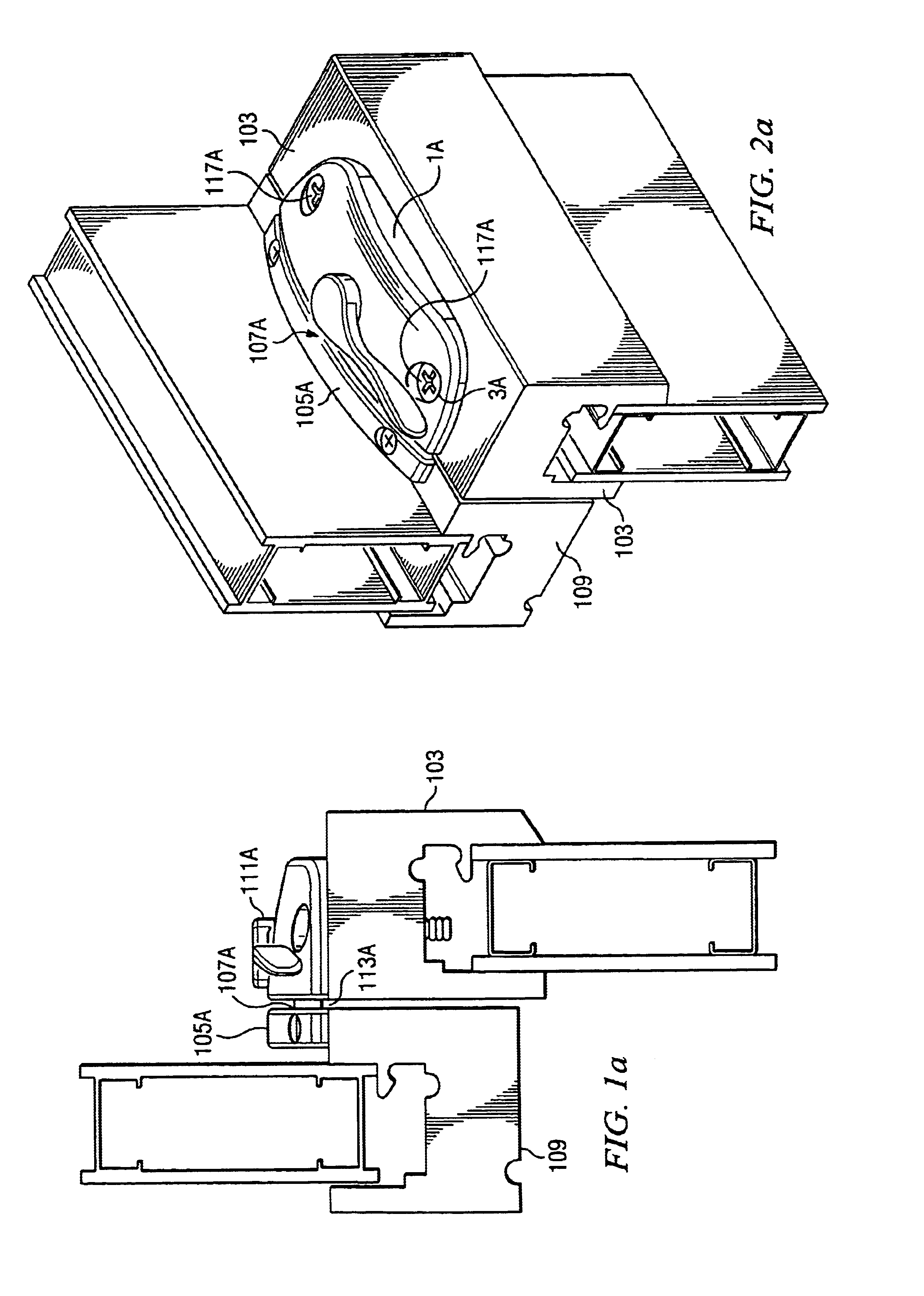
Referring to FIGS. 1 and 2, there are shown side and perspective views, respectively, of upper 109 (which is generally the outer) and lower 103 window sashes. A keeper 105 having a slot 107 is disposed parallel to the upper surface of the check rail of the upper sash 109 and secured thereto. The sash lock 111 contains a movable slide 113 (7 in FIG. 3), preferably of spring steel, and is disposed on the upper surface of the check rail of the lower sash 103.

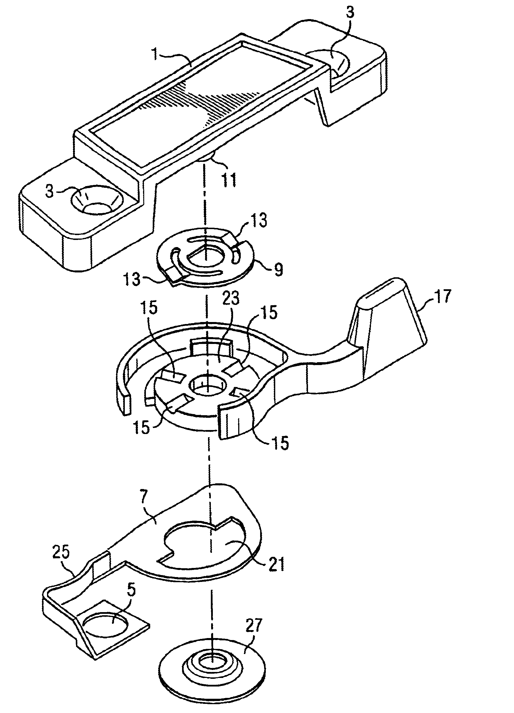
Referring now also to FIG. 3, there is shown an exploded view of the sash lock assembly 111 in accordance with the present invention. The sash lock assembly 111 is attached to an interior window check rail 103 by screws or the like 117 which pass through the screw holes 3 of the housing 1 and holes 5 in spring steel slide 7 (113). The lock is assembled by placing a fixed detent spring 9 around the fixed axial shaft portion 11 of the housing 1 (better shown in FIG. 4) with detents 13 on opposing sides of the spring 9 entering a pair...


PUM


Abstract

A sash lock apparatus which includes a keeper disposable on a first window sash and having a keeper aperture therein for lockingly receiving therein a selectively retractable element from a sash lock and the sash lock having the selectively retractable element disposable on a second window sash wherein the first and second window sashes are disposed for movement in a direction parallel to each other. The sash lock includes a rotatable lever having a tab extending therefrom and a spring slide deformable by rotation of the rotatable lever and movement of the tab against the spring slide for selectively causing a portion of the spring slide to enter and retract from the aperture to cause locking and unlocking of the first and second window sashes relative to each other. The spring slide includes a central aperture, the tab extending into the central aperture, rotation of the tab with the rotatable lever causing deformation of the spring slide and one of movement of the spring slide into or out of the keeper aperture. The housing has a shaft secured to the spring slide, the rotatable lever being rotatable about the shaft. The spring slide is preferably a spring steel slide. The apparatus may further include a member having member detents therein and secured to the shaft and rotatable member detents disposed on the rotatable member for entry into at least one selected member detent upon rotation of the rotatable member to one of an open or closed position.

Description

FIELD OF AND BACKGROUND OF THE INVENTIONThis invention relates to a window or sash lock assembly and, more specifically to such an assembly which cannot be opened from the window exterior by potential burglars and the like.The problem of securing windows and especially sash type windows from unlocking due to manipulation of the sash lock from the window exterior has been well known in the prior art and many potential solution of this problem appear in the prior art.A first example of such a sash lock is shown in the patent of Subliskey (U.S. Pat. No. 6,116,665) which has a housing, a rotating assembly mounted in the housing, the rotating assembly including a handle rotatable in the housing and movable between open and closed position, a shaft connected to the handle and rotatable with the handle, a cam connected to the shaft, and contoured to engage a keeper, a slide plate mounted to the housing and slidable between a retracted position in which it is within the housing and an exten...

Claims


Application Information

Patent Timeline
IPC IPC(8): E05B17/20E05B17/00E05C3/00E05C3/04E05C7/00
CPCE05B17/2003E05C3/046Y10S292/47E05C2007/007Y10T292/1041
Inventor COLEMAN, JOHN D.HUFNAGLE, RAYMOND
Owner HOWARD BERGER CO
Why Eureka
Try Eureka