
Conversion sleeve and optical adapter

Inactive Publication Date: 2005-03-29
YKK CORP
View PDF10 Cites 19 Cited by
  • Summary
  • Abstract
  • Description
  • Claims
  • Application Information

AI Technical Summary

Benefits of technology

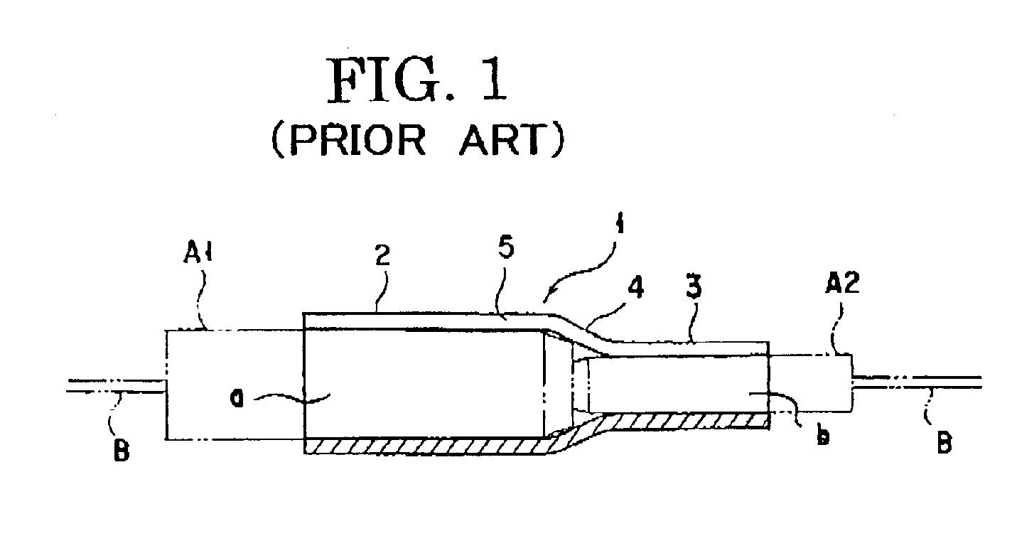
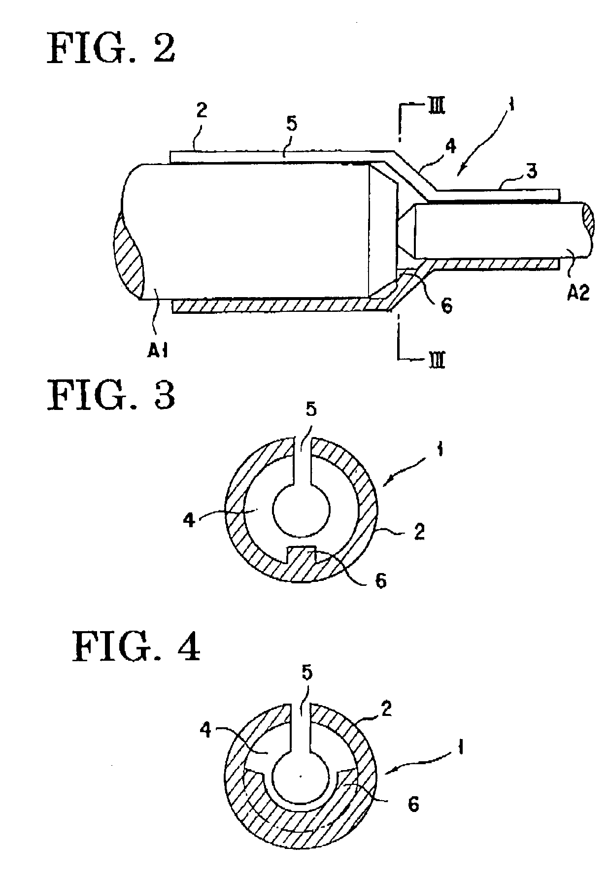
It is, therefore, an object of the present invention to solve the problems of the conventional technology as mentioned above and to provide a conversion sleeve which can establish the PC contact of the ferrules of different diameters inserted thereinto always in a fixed position, thereby lowering the axial deviation (offset) of optical fibers as much as possible and attaining stable connection of the ferrules having different diameters with constantly low connection loss, without causing any scattering of results.
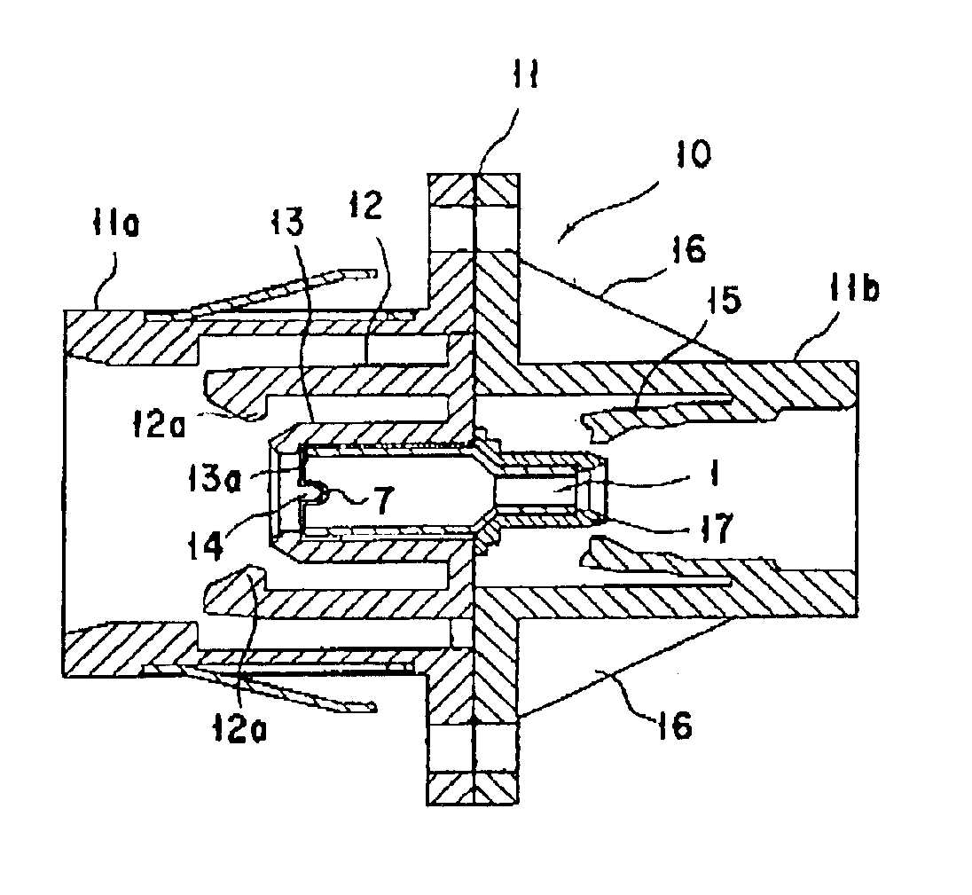
A further object of the present invention is to provide an optical adapter, particularly a conversion adapter, which can prevent rotation of an alignment sleeve, thereby lowering the axial deviation (offset) of ferrules (optical fibers) inserted therein as low as possible and attaining stable optical connection with constantly low connection loss, without causing any scattering of results.

Problems solved by technology

Since the highly accurate processing is difficult, it poses the problem that the processing cost becomes high.
In this case, the problem of deviation in the contact position will arise.
Furthermore, if the length of the leading part of the ferrule changes due to re-polishing or other causes, it will pose the problems that the deviation in the contact position will occur similarly, the offset becomes large, and thus the connection loss becomes large.
That is, its weak point is that the contact position is uncertain.
As described above, in the elastic conversion sleeve which is provided with a slit to acquire suitable retaining force, there is a problem that the PC contact position will vary with the connectors to be used.
Therefore, there is a problem that, when the alignment sleeve rotates, it causes a deviation between the axes of the ferrules (the cores of the optical fibers) and the change in the optical characteristics.
This poses the problem that the connection loss becomes larger.

Method used


Image

  • Conversion sleeve and optical adapter
  • Conversion sleeve and optical adapter
  • Conversion sleeve and optical adapter

Examples


Embodiment Construction

As described above, in the conversion sleeve accompanied by elastic deformation, for example, when the SC ferrule and the MU ferrule are connected, a slight axial inclination (about 0.1°) may arise. In the case of the inclination of 0.1°, if the contact position shifts 0.5 mm in the axial direction, the axial deviation (offset) of about 1 μm of optical fibers will arise. This will result in such a problem that the connection loss becomes large and the variation in the connection loss arises.

On the contrary, in the conversion sleeve of the present invention, since the ferrule insertion stop part is formed on the inner circumferential surface of the tapered diameter part of the conversion sleeve mentioned above and / or the inner circumferential surfaces of the large diameter part and the small diameter part adjacent to the tapered diameter part, the connection is performed in such state that the leading end face of one ferrule inserted into the sleeve abuts against this ferrule inserti...


PUM


Abstract

In a conversion sleeve comprising a large diameter part, a small diameter part, and a tapered diameter part interconnecting said two parts, a ferrule insertion stop part is formed on an inner circumferential surface of the tapered diameter part and / or inner circumferential surfaces of the large diameter part and the small diameter part adjacent to the tapered diameter part. An optical adapter comprises a split sleeve having a slit formed therein throughout the entire length in the longitudinal direction thereof, particularly a conversion sleeve, and an adapter housing having a sleeve retaining part in which the sleeve is inserted and retained. The sleeve retaining part is provided with an engagement part comprising a recessed portion or / and a projected portion. The split sleeve is provided with a counter engagement part comprising a projected portion or / and a recessed portion which engages with the recessed portion or / and the projected portion of the engagement part.

Description

BACKGROUND OF THE INVENTION1. Field of the InventionThis invention relates to a conversion sleeve and an optical adapter to be used for interconnecting optical connectors of the optical fiber cable ends which are used in optical communications, particularly the conversion sleeve and the conversion adapter to be used for interconnecting optical connectors containing ferrules having different diameters.2. Description of the Prior ArtIn an optical connector which is used to facilitate the connection and the disconnection of two optical fibers or of an optical fiber and other optical element, like the SC type optical connector, for example, the predominantly used system comprises fitting one end of an optical fiber into an axial through-hole of a ferrule and inserting two ferrules thus prepared into an alignment sleeve of an optical adapter through the opposite ends thereof to abut end faces of the ferrules against each other.The use of the sleeve for aligning the ferrules each having a...

Claims


Application Information

Patent Timeline
IPC IPC(8): G02B6/38
CPCG02B6/3825
Inventor TAKEDA, HIDEKIKAWAHARA, YASUTOMONOZUE, KENJIYAMAGUCHI, TADASHI
Owner YKK CORP
Learn More