
Optical fiber and method for producing same

A manufacturing method and optical fiber technology, applied in the direction of manufacturing tools, clad optical fiber, glass manufacturing equipment, etc., to achieve the effects of improved dispersion characteristics, low bending loss, and low connection loss

Pending Publication Date: 2020-03-24
THE FUJIKURA CABLE WORKS LTD
View PDF8 Cites 0 Cited by
  • Summary
  • Abstract
  • Description
  • Claims
  • Application Information

AI Technical Summary

Problems solved by technology

Therefore, in the optical fiber described in Patent Document 1, there is room for improvement in dispersion characteristics.

Method used


Image

  • Optical fiber and method for producing same
  • Optical fiber and method for producing same
  • Optical fiber and method for producing same

Examples


Embodiment Construction

[0031] 〔Structure of optical fiber〕

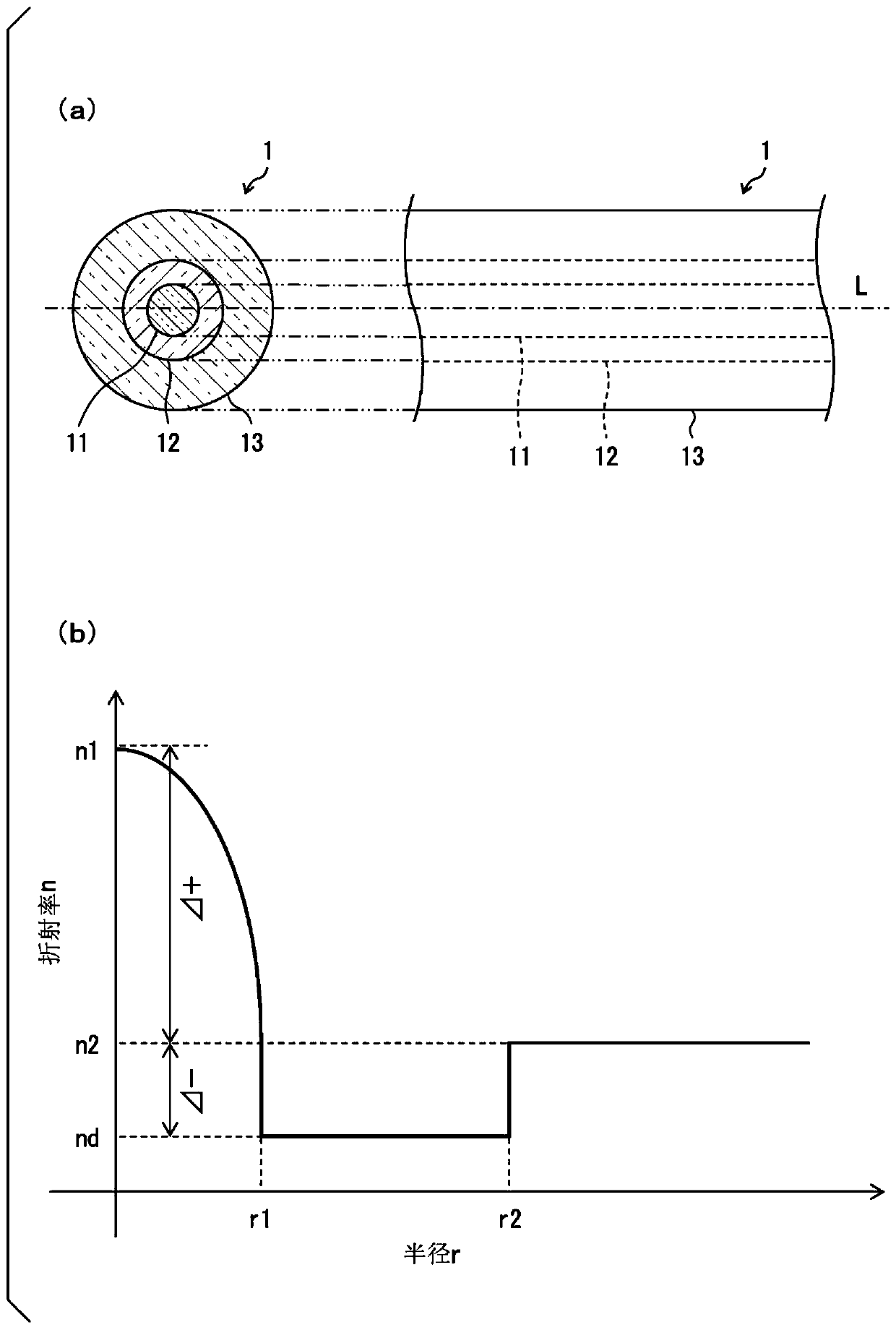
[0032] refer to figure 1 , the structure of the optical fiber 1 according to the embodiment of the present invention will be described. exist figure 1 Among them, (a) is a sectional view (left) and a side view (right) of the optical fiber 1 , and (b) is a graph showing the refractive index distribution of the optical fiber 1 . figure 1 The cross-sectional structure shown in (a) is the same in each cross-section of the optical fiber 1 perpendicular to the central axis L of the optical fiber 1 .

[0033] The optical fiber 1 is a cylindrical structure mainly composed of quartz glass, such as figure 1 As shown in (a), the core 11 having a circular (radius r1) cross-section, the depressed layer 12 having a cross-section of a ring (inner radius r1, outer radius r2) surrounding the core 11, having The cladding layer 13 is constituted by a cross-section in the shape of a ring (inner radius r2, outer radius r3) surrounding the depressed layer 1...


PUM

PropertyMeasurementUnit
wavelengthaaaaaaaaaa
diameteraaaaaaaaaa

Abstract

The present invention relates to an optical fiber and a method for producing the same. The optical fiber is provided with: a core, a depressed layer surrounding the core; and a clad surrounding the depressed layer, wherein the refractive index distribution of the core is an [alpha]-power distribution having an exponent [alpha] of 3.5-6, the absolute value |[delta]-| of the relative refractive index difference [delta]- between the depressed layer and the clad is set to be within 0.01-0.045%, the ratio of the radius r1 of the core to the outer radius r2 of the depressed layer, that is, r1 / r2, isset to be within 0.2-0.6, the 22 m cable cutoff wavelength [lambda]cc is 1260 nm or less, and the mode field diameter (MFD) at a wavelength of 1310 nm is 8.6-9.5 [mu]m.

Description

[0001] Cross References to Related Applications [0002] This application claims the priority of Japanese Patent Application No. 2017-139349 filed in Japan on July 18, 2017 and Japanese Patent Application No. 2018-043636 filed in Japan on March 9, 2018, the contents of which are cited here. technical field [0003] The present invention relates to an optical fiber having a depressed layer between the core and the cladding. Moreover, it relates to the manufacturing method of manufacturing the above-mentioned optical fiber. Background technique [0004] Patent Document 1 discloses an optical fiber having a depressed layer between a core and a cladding. In Patent Document 1, it is described that by setting the relative refractive index difference Δ of the depressed layer relative to the cladding layer - And the ratio r1 / r2 of the radius r1 of the fiber core relative to the outer peripheral radius r2 of the depressed layer is optimized, so that the mode field diameter can be m...

Claims


Application Information

Patent Timeline
Patent Type & Authority Applications(China)
IPC IPC(8): G02B6/036C03B37/018G02B6/028
CPCG02B6/03627G02B6/02214G02B6/0281
Inventor 丸山辽
Owner THE FUJIKURA CABLE WORKS LTD
Learn More