
Optical waveguide chip with micro-optical gyroscope Sagnac effect and preparation method thereof

An optical waveguide and micro-optic technology, applied in the field of optical waveguide, can solve the problems of large bending loss, serious bending loss, interference fringe interference of optical waveguide, and achieve the effect of small cross point loss, small bending loss, and avoiding interference.

Inactive Publication Date: 2014-09-10
INST OF SEMICONDUCTORS - CHINESE ACAD OF SCI
View PDF3 Cites 7 Cited by
  • Summary
  • Abstract
  • Description
  • Claims
  • Application Information

AI Technical Summary

Problems solved by technology

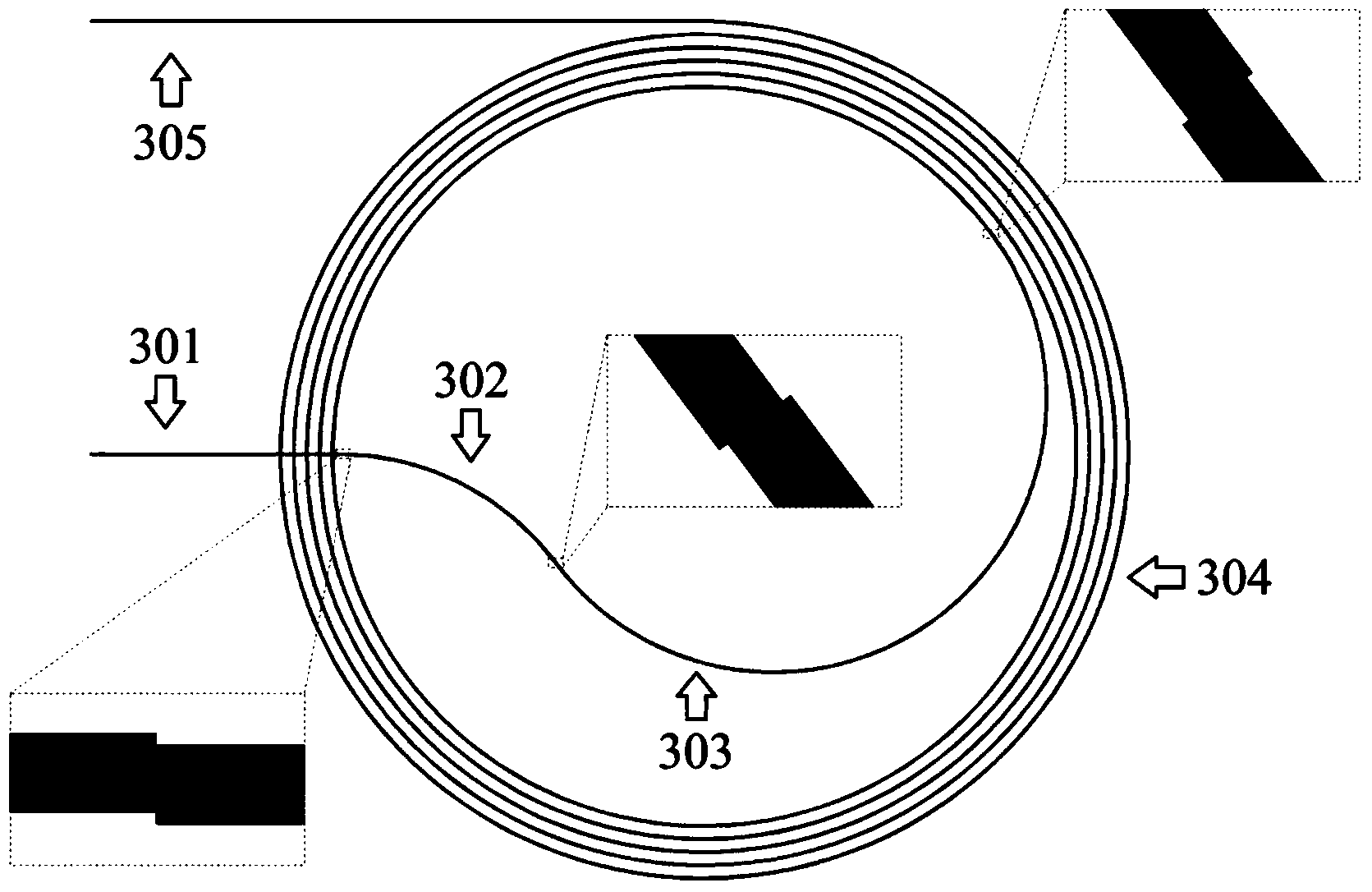
On the one hand, if the intersection angle is too small, part of the light passing through the spiral ring will be coupled into the spiral ring, resulting in a certain amount of light loss and interference to the final interference fringes.
On the other hand, due to the requirement of miniaturization, the radius of the helical optical waveguide needs to be as small as possible. The smaller the radius, the greater the bending loss of the optical waveguide, especially the path where the innermost circle passes through the helical ring. Small connection points with sudden changes in curvature, the bending loss of this path is relatively serious

Method used


Image

  • Optical waveguide chip with micro-optical gyroscope Sagnac effect and preparation method thereof
  • Optical waveguide chip with micro-optical gyroscope Sagnac effect and preparation method thereof
  • Optical waveguide chip with micro-optical gyroscope Sagnac effect and preparation method thereof

Examples


Embodiment Construction

[0032] In order to make the object, technical solution and advantages of the present invention clearer, the present invention will be described in further detail below in conjunction with specific embodiments and with reference to the accompanying drawings. It should be noted that, in the drawings or descriptions of the specification, similar or identical parts all use the same figure numbers. Implementations not shown or described in the accompanying drawings are forms known to those of ordinary skill in the art. Additionally, while illustrations of parameters including particular values ​​may be provided herein, it should be understood that the parameters need not be exactly equal to the corresponding values, but rather may approximate the corresponding values ​​within acceptable error margins or design constraints. The directional terms mentioned in the embodiments, such as "upper", "lower", "front", "rear", "left", "right", etc., are only referring to the directions of the...


PUM


Abstract

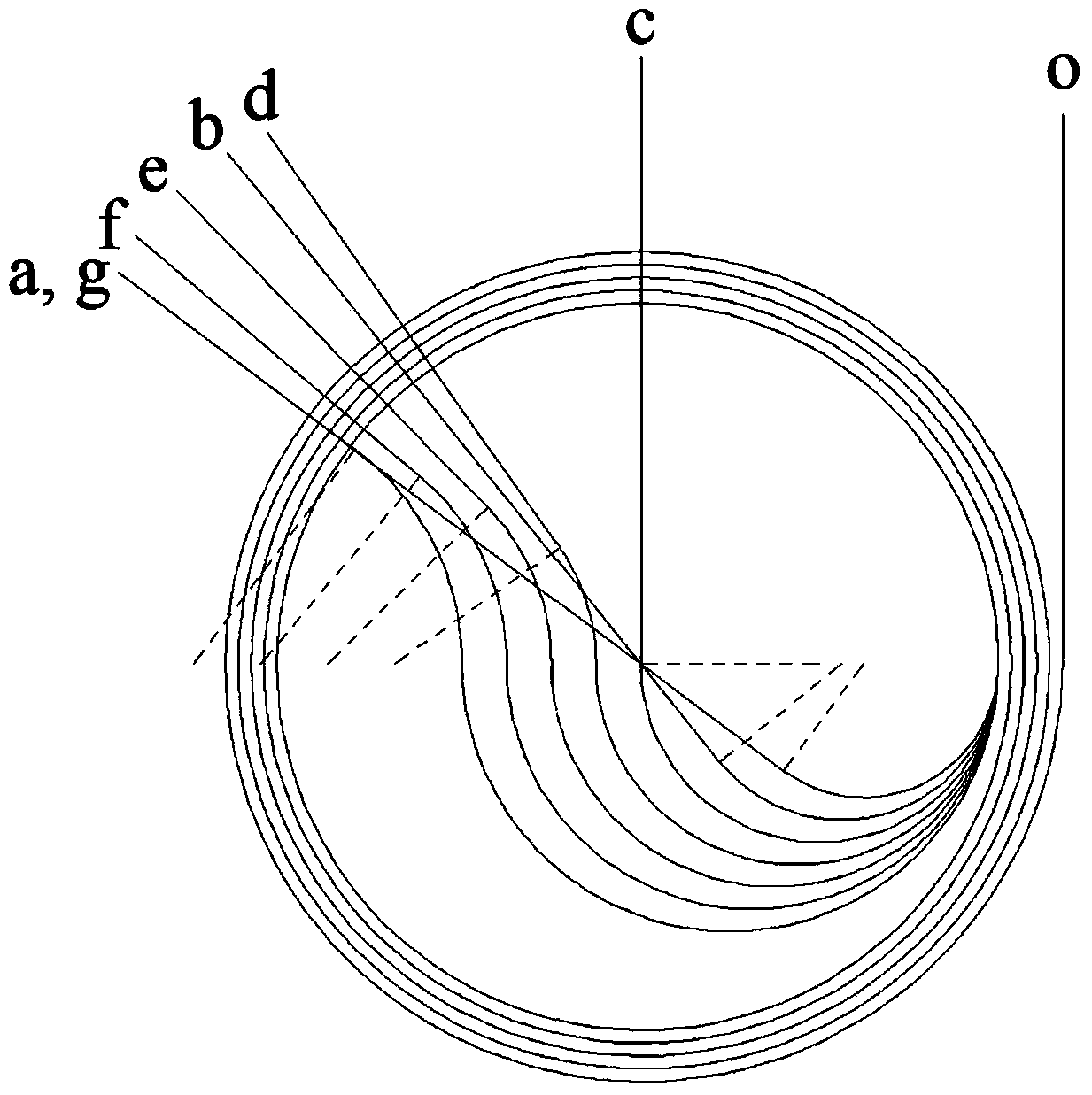
The invention discloses an optical waveguide chip with a micro-optical gyroscope Sagnac effect and a preparation method thereof. The optical waveguide chip comprises a substrate, an SiO2 (Silicon Dioxide) lower cladding layer and an SiO2 core area light guide, wherein the SiO2 core area light guide comprises an input straight waveguide part, two arc-shaped bend waveguide parts, an Achimedean spiral bending waveguide part and an output straight waveguide part; an input straight waveguide part of the SiO2 lower cladding layer and a spiral ring of the Achimedean spiral bending waveguide part are vertically crossed, so as to reduce the loss of an X Achimedean spiral bending waveguide part; two arc bending waveguide parts are oppositely connected, an input direct waveguide terminal and a starting end of the Achimedean spiral bending waveguide part are smoothly connected, and an optimal dislocation offset can be guided on the end plane of a wave guide connecting place, so that the bending loss is less. According to the optical waveguide chip, the sensitivity of the gyroscope can be improved, and the noise of the gyroscope can be reduced.

Description

technical field [0001] The invention relates to the field of optical waveguide technology, in particular to a micro-optical gyroscope Sagnac effect optical waveguide chip and a preparation method thereof. Background technique [0002] Micro-optical gyroscope is a new generation of gyroscope developed after mechanical gyroscope, laser gyroscope and fiber optic gyroscope. It replaces optical fiber with optical waveguide as the Sagnac effect sensitive element, and integrates light source, detector, processing circuit, etc. on the same silicon chip, so as to realize a new generation of gyroscope with smaller volume and higher reliability. The less lossy the optical waveguide, the higher the sensitivity of the gyroscope. At present, the loss of optical waveguides in planar technology is much larger than that of optical fibers. How to reduce the loss of optical waveguides is a key issue in realizing high-sensitivity micro-optical gyroscopes. The interferometric micro-optical gyr...

Claims


Application Information

Patent Timeline
Patent Type & Authority Applications(China)
IPC IPC(8): G02B6/122G02B6/13
Inventor 杨添舒刘雯时彦朋马静张端郑婉华王晓东杨富华
Owner INST OF SEMICONDUCTORS - CHINESE ACAD OF SCI
Learn More