
Optical fiber, optical fiber connecting method, and optical connector

A technology of optical fiber and connecting part, which is applied to optical fiber connectors, connection methods between single-mode optical fibers and the fields of optical connectors, optical fibers and their optical fiber connectors. It can solve the problems of large changes in temperature characteristics and increased connection losses, and achieve Effects of preventing deterioration of mechanical strength, prevention of strength deterioration, and easy connection

Inactive Publication Date: 2006-05-17
HITACHI CABLE +1
View PDF10 Cites 12 Cited by
  • Summary
  • Abstract
  • Description
  • Claims
  • Application Information

AI Technical Summary

Problems solved by technology

[0041] Therefore, the conventional mechanical joint 391 has a problem that the temperature characteristic of the connection loss changes greatly, and the connection loss increases especially in the low temperature region.

Method used


Image

  • Optical fiber, optical fiber connecting method, and optical connector
  • Optical fiber, optical fiber connecting method, and optical connector
  • Optical fiber, optical fiber connecting method, and optical connector

Examples


Embodiment approach 1

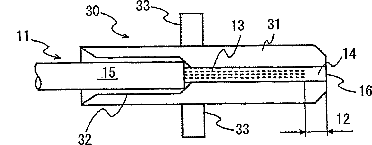
[0119] figure 1 It is a side view showing a photonic crystal fiber (PCF) according to a preferred embodiment 1 of the present invention.

[0120] First, PCF11 of this embodiment and Figure 5 PCF41 explained in , so its detailed description will be omitted. However, the optical fiber is used in the state of an optical fiber core covered by a coating made of UV resin around the cladding, and the connecting part connected to a ferrule or other connector is stripped Use in such a way that the coating is removed.

[0121] like figure 1 As shown, the cavity 13 near the connection end 12 of the PCF 11 is filled with a UV curable resin 14 having a lower refractive index than quartz as a filler. The UV curable resin 14 is liquid at normal temperature before use, and is cured by irradiating ultraviolet rays. The UV curable resin used in this embodiment is the epoxy-based fluorine-containing UV curable resin 14 whose refractive index after curing is adjusted to 1.42.

[0122] The ...


PUM


Abstract

An optical fiber in which the hollows near the connecting end of the optical fiber having a plurality of hollows around the core are filled with a light-transmitting substance such as resin or glass having a lower refractive index than quartz-based materials. The connecting portion of the optical fiber connects an optical fiber having a plurality of hollow holes in the cladding around the core to another optical fiber through a refractive index lower than that of the core at the lowest temperature in actual use. A matching agent is used to align and connect the optical fiber with the other optical fiber.

Description

[0001] This application is based on Japanese Patent Application Nos. 2003-189724, 2003-189655, 2003-194476, 2003-189726, and 2003-346905, and the entire contents of these Japanese applications are incorporated herein by reference. technical field [0002] The present invention relates to an optical fiber having a plurality of hollow holes around the core, and more particularly to a connection method between a photonic crystal optical fiber and a single mode fiber having a mode field diameter larger than the same, and an optical connector . [0003] In addition, the present invention also relates to a sealing structure for an end portion of an optical fiber having a core having a high refractive index and a cladding having a small refractive index surrounding it and having a plurality of holes extending toward the axis of the optical fiber in the cladding and its sealing method. [0004] In addition, the present invention also relates to an optical fiber having a core with a h...

Claims


Application Information

Patent Timeline
Patent Type & Authority Applications(China)
IPC IPC(8): G02B6/00G02B6/24G02B6/10G02B6/255G02B6/26G02B6/38
Inventor 黑泽芳宣姚兵大园和正立藏正男中居久典仓岛利雄荒木荣次平松克美
Owner HITACHI CABLE
Learn More