Mounting system for supporting a ceiling fan assembly

a technology for mounting systems and ceiling fans, which is applied in the direction of machines/engines, liquid fuel engines, filing appliances, etc., can solve the problems of affecting the installation of ceiling fans, and affecting the service life of ceiling fans

Inactive Publication Date: 2005-03-29
HUNTER FAN
View PDF8 Cites 39 Cited by
  • Summary
  • Abstract
  • Description
  • Claims
  • Application Information

AI Technical Summary

Benefits of technology

In a preferred form of the invention, a mounting system for supporting a ceiling fan assembly of the type having a motor, a motor housing, a plurality of blades and a downrod to a support surface comprising a mounting bar coupled to the support surface, a mounting plate coupled to the support surface, a suspending member coupled to the downrod of the ceiling fan assembly, a canopy coupled to the downrod, and adjustable coupling means which couples the canopy to the moun...

Problems solved by technology

Notwithstanding the widespread use of ceiling fans, the installation of ceiling fans remains problematic.
Twisted wires are apt to break or be damaged and will require repair or replacement.
Additionally, the rotation of the ceiling fan assembly during installation makes wiring the ceiling fan assembly to the electrical wires within the ceiling more difficult.
With both bracket mounting systems and conventional canopy mounting systems, additional installation problems are common.
For instance, these systems permit the installer only limited physical access through the smal...

Method used


Image

  • Mounting system for supporting a ceiling fan assembly
  • Mounting system for supporting a ceiling fan assembly
  • Mounting system for supporting a ceiling fan assembly

Examples


first embodiment

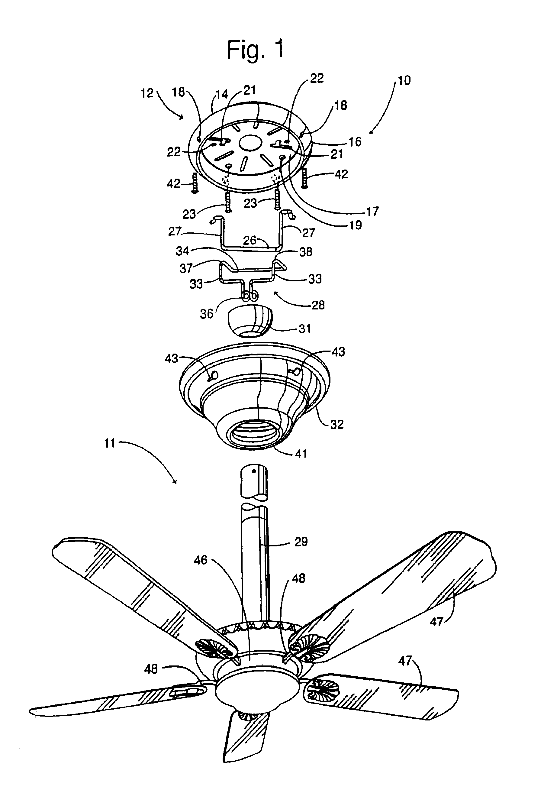
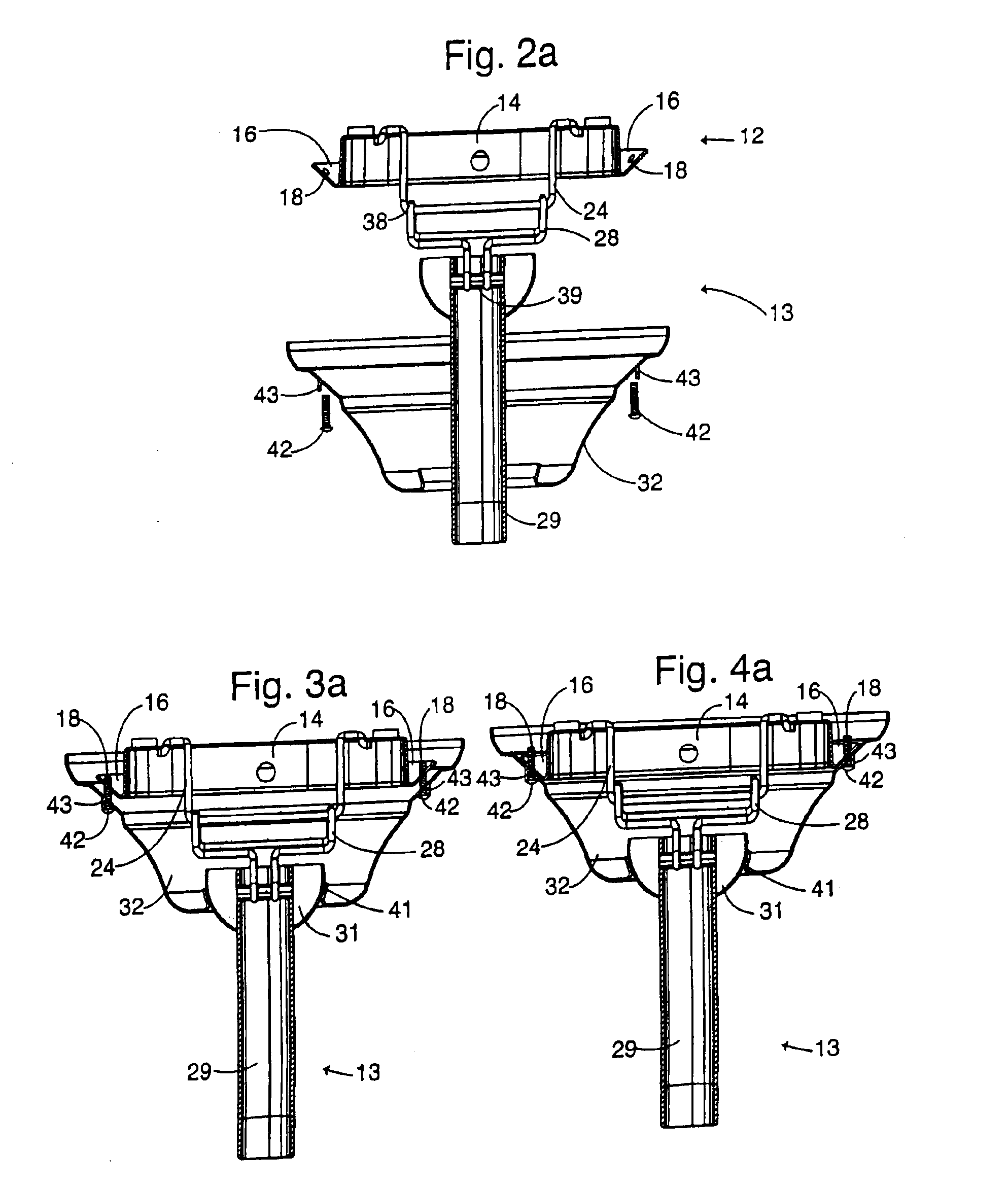
The ceiling fan assembly 101 may be removed from the ceiling C in substantially the same manner as the ceiling fan assembly 11 of the The screws 148 are simply unthreaded thereby causing the hanging member 122 to again receive the mounting bar 116 within its hooking portion of horizontal member 136 and curved portion 134. The operator may then lift the hanging member 122 over the mounting bar 116 to completely separate the ceiling fan assembly 101 from the ceiling C.

The mounting bar 116 in combination with the hanging member 122 prevents the rotation of the downrod 29 and ceiling fan assembly 101 during mounting and operation and allows for an installer to momentarily relieve the weight of the fan assembly 101 from himself during an interim step prior to permanently mounting the ceiling fan assembly 101 to the ceiling. It should be understood that although the preferred embodiment depicts screws 148 as a fastening or drawing means, other means such as bolts, latches, clasps, locks ...

second embodiment

In a third alternative embodiment, the ceiling fan assembly 151 depicted in FIG. 9 is essentially the same as the ceiling fan assembly 101 of the second embodiment, the only difference being that in this embodiment the tab 152 extends generally inward from the canopy 153 and is received in a slot 154 that extends into the mounting plate 155, i.e., the relative positions of the tab and slot relative to the canopy and mounting plate are reversed.

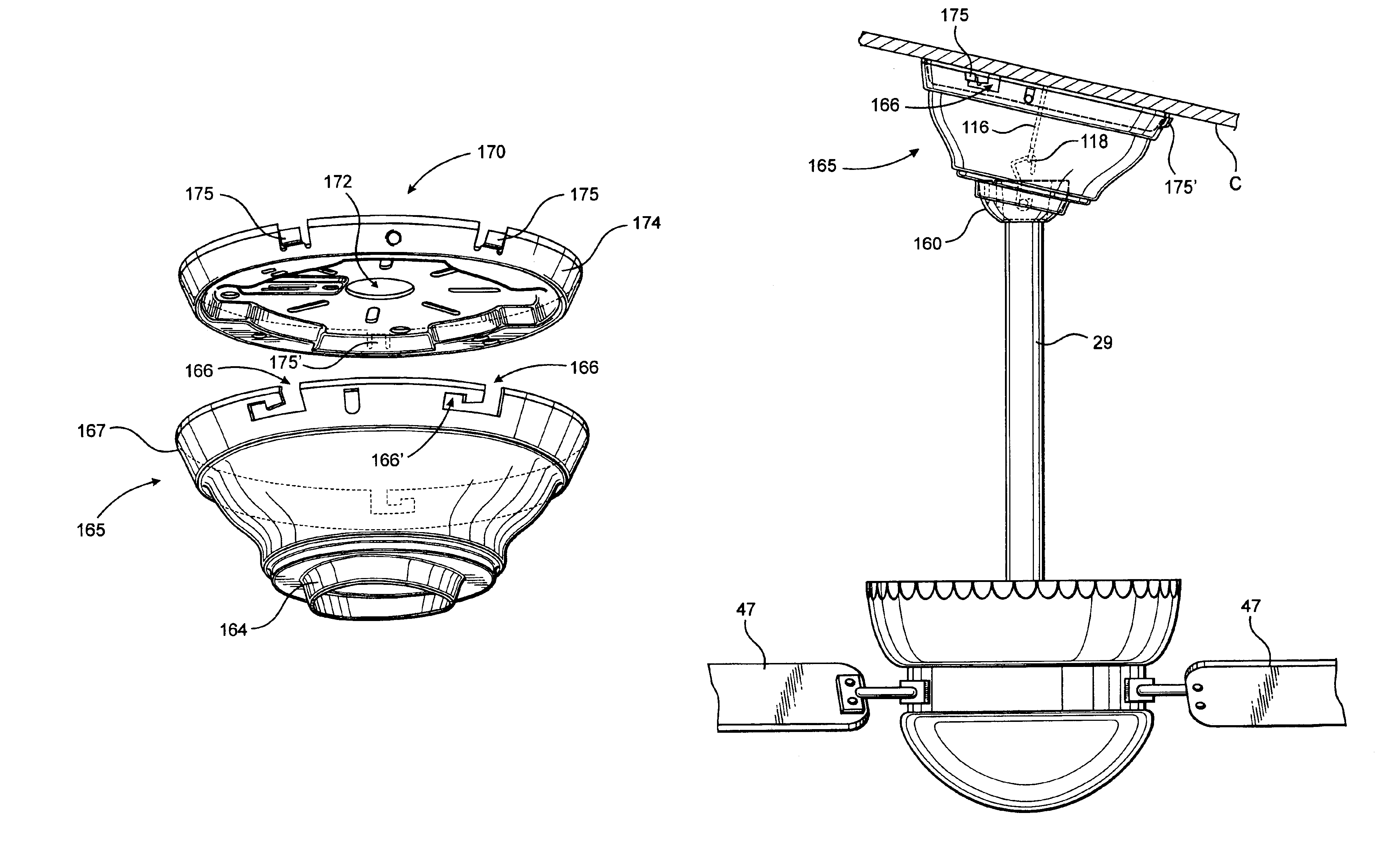
A fourth alternative embodiment is shown in FIGS. 10-13. This embodiment preferably includes a multi-lobed ball 160 that is illustrated in FIGS. 10A-10C to which the fan downrod is connected. Here the ball has three radially outwardly extending lobes 161, 162, and 163. The exterior shape of the ball is complementary to the interior shape of the seat 164 of the canopy 165 shown in FIGS. 11 and 12 into which seat the ball is nested. As more fully explained in U.S. Pat. No. 6,234,757, this design of the ball and its socket seat in the canopy enab...


PUM


Abstract

A ceiling fan mounting system for mounting a fan to a canted ceiling with its fan blades rotated in a horizontal plane. The system has an elongated hanger bar (118) suspended from a ceiling mounting plate (170). The fan downrod is attached to a multi-lope ball (160) that is seated in a canopy seat (182). The canopy can be mounted to the ceiling plane in only one position, a position that orients the hanger bar parallel to the canted ceiling, parallel to the mounting plate and parallel to the fan blades horizontal plane of rotation.

Description

TECHNICAL FIELDThis invention relates to a mounting system for supporting a ceiling fan assembly.BACKGROUND OF THE INVENTIONCeiling fans have become an increasingly popular supplementary means of creating an airflow within both commercial and residential buildings. Notwithstanding the widespread use of ceiling fans, the installation of ceiling fans remains problematic.With conventional mounting systems, the weight of the ceiling fan assembly, which includes the ceiling fan motor, motor housing, downrod, blades and blade irons, is supported by either a mounting bracket or a canopy. These mounting brackets or canopies typically include slotted openings extending from their outer edges to their centers, which are adapted to accept and retain the top end of the downrod which commonly ends in a ball joint.When a bracket mounting system is used, the slotted mounting bracket is mounted either directly or indirectly to the ceiling at the mounting location of the anticipated connection of th...

Claims


Application Information

Patent Timeline
IPC IPC(8): F04D25/08F04D25/02F04D29/60
CPCF04D29/601F04D25/088
Inventor PEARCE, RICHARD A.
Owner HUNTER FAN
Why Eureka
Try Eureka