Electric fence insulators

a technology of electric fences and insulators, applied in the field of insulators, can solve the problems of cumbersome use of separate insulators, desire improvement, etc., and achieve the effect of reducing stress and stress

Inactive Publication Date: 2005-03-29
WOODSTREAM CORP
View PDF22 Cites 20 Cited by
  • Summary
  • Abstract
  • Description
  • Claims
  • Application Information

AI Technical Summary

Benefits of technology

In a preferred embodiment, the insulator includes an elongate body of molded plastic construction mountable to a support and including a wire mounting face. A first rigid tab is positioned adjacent the wire mounting face and has an opening for passage of the first wire and a curved closed end configured for bearing against the first wire to provide a radius for the first wire to curve around to reduce stresses on the first wire as it under

Problems solved by technology

The use of separate insulators, however

Method used


Image

  • Electric fence insulators
  • Electric fence insulators
  • Electric fence insulators

Examples


Embodiment Construction
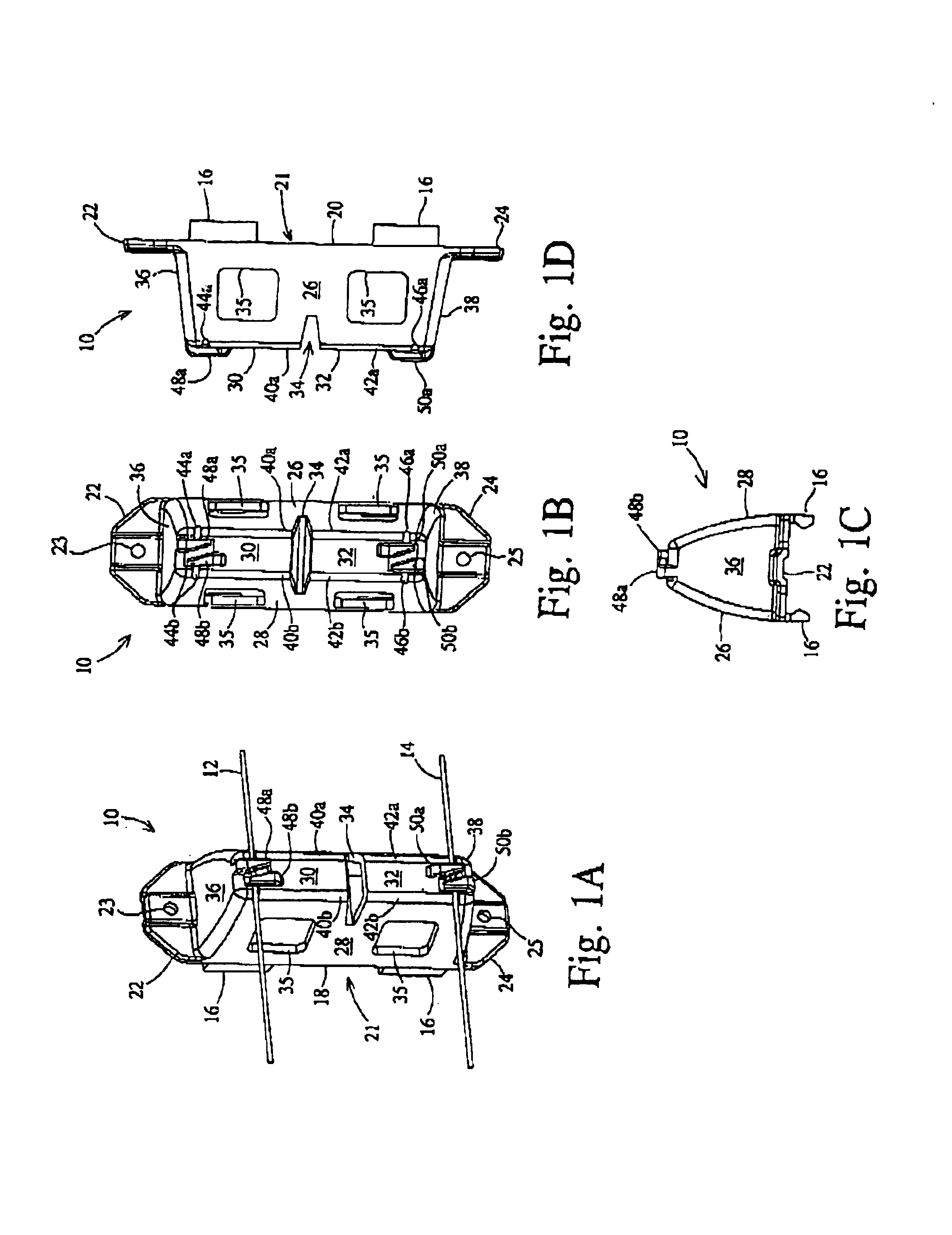
FIGS. 1A-1D

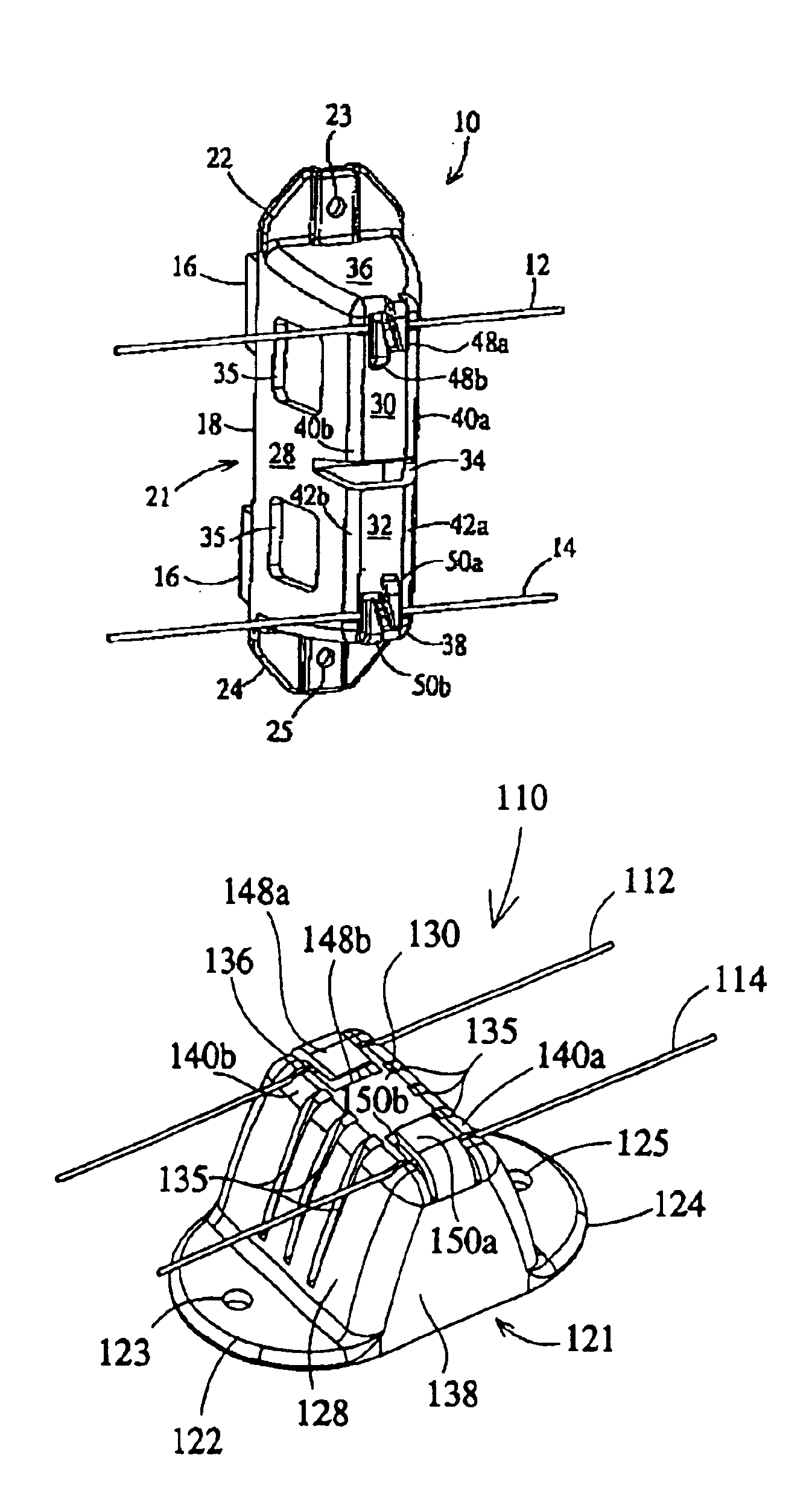
With reference to FIGS. 1A-1D, there is shown a fence insulator 10 in accordance with a preferred embodiment of the invention. The insulator 10 is shown in FIG. 1A having a ground wire 12 and current carrying wire 14 installed thereon adjacent a mounting face thereof to maintain the wires 12 and 14 in a desired spaced apart relationship. Heretofore, separate insulators have been used with electric fences of the type having a ground wire and a current carrying wire. That is, on a post, a first insulator is used to support the current carrying wire, while a second insulator is used to support the ground wire. The present invention now enables the use of a single or unitary insulator on a post or support to support both the current carrying wire and the ground wire to maintain them separate and in electrical isolation from one another.

The insulator 10 is preferably of one-piece molded plastic construction and configured to be mounted to a vertically oriented metal or wood po...


PUM


Abstract

A molded plastic fence insulator including a pair of spaced apart sidewalls connected by a connecting wall, aligned grooves defined across the connecting wall, and retention members associated with the aligned grooves and configured for receiving the wires underneath a portion thereof.

Description

FIELD OF THE INVENTIONThis invention relates generally to insulators for electric features. More particularly, this invention relates to insulators mountable to a support structure for supporting and maintaining a pair of electric fence wires in a spaced apart relationship.BACKGROUND AND SUMMARY OF THE INVENTIONElectric fences of the type utilizing a ground wire, a current carrying wire, and a source of electrical current are known. The ground wire and the current carrying wire are conventionally spaced apart and positioned generally parallel to one another using separate insulator devices. The spacing between the wires are such that an animal coming in contact with the fence will contact both wires. This creates a current path to complete the circuit such that the animal receives a mild electrical shock.The wires are often suspended or supported from a support structure, such as a board, or a metal or wood post. It is important to electrically isolate or insulate the wires from the...

Claims


Application Information

Patent Timeline
IPC IPC(8): H01B17/14
CPCH01B17/145Y10S256/03
Inventor BURDICK, BRETT R.
Owner WOODSTREAM CORP
Why Eureka
Try Eureka