Graded-index optical fiber

a technology of optical fiber and refractive index, applied in the field of optical fiber, can solve the problem of no appropriate method relating to multimode optical fiber

Active Publication Date: 2005-03-29
SAMSUNG ELECTRONICS CO LTD
View PDF7 Cites 8 Cited by
  • Summary
  • Abstract
  • Description
  • Claims
  • Application Information

AI Technical Summary

Problems solved by technology

However, in the prior art there is no appropriate method relating to the multimode optical fiber.

Method used


Image

  • Graded-index optical fiber
  • Graded-index optical fiber
  • Graded-index optical fiber

Examples


Embodiment Construction

Now, embodiments of the present invention will be described in detail with reference to the annexed drawings. In the following description, a detailed description of known functions and configurations incorporated herein will be omitted when it may obscure the subject matter of the present invention.

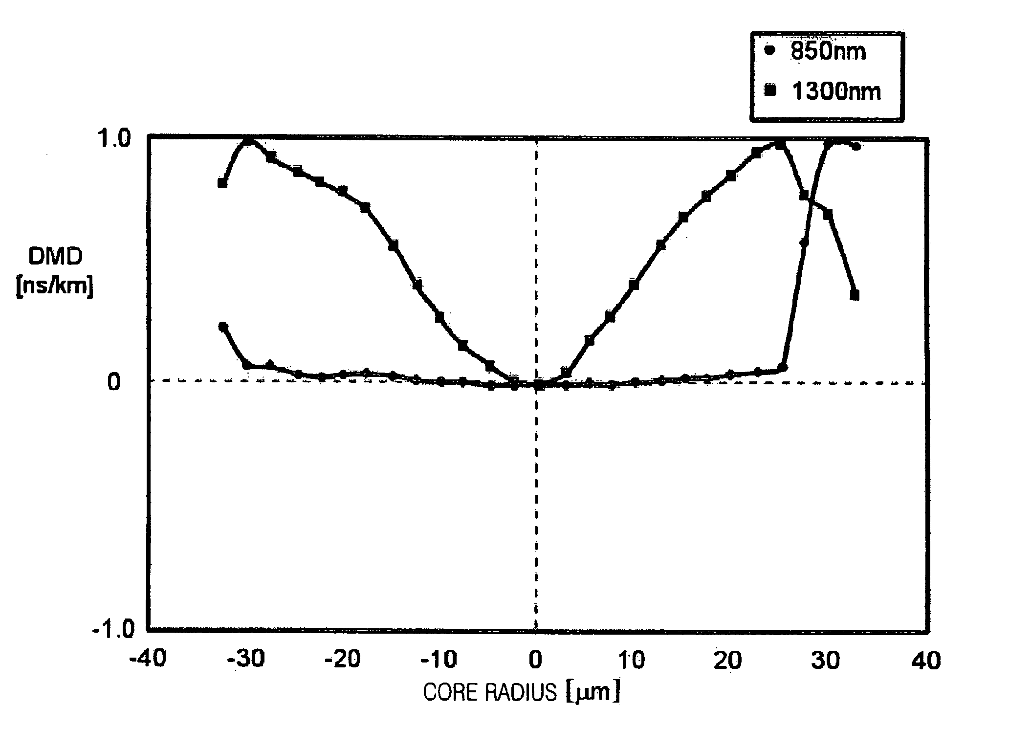
As described above, the attenuation and bandwidth characteristics of a graded-index optical fiber are important factors that determine the performance of the graded-index optical fiber. In addition to these optical characteristics, the differential mode delay (DMD) is another important factor. The DMD between transmission modes through a multimode optical fiber does not have a large effect at low transmission rates, but the DMD is a factor capable of degrading transmission quality at transmission rates of one gigabit / second or more. Despite this factor, conventionally, in order for the performance of the graded-index optical fiber to be evaluated only the bandwidth was measured. Referrin...


PUM


Abstract

An optical fiber having a core that has a graded refractive index profile is disclosed. A clad surrounds the core and traps light within the core. A difference between differential mode delays (DMDs) at wavelengths of about 1300 nm and about 850 nm within the core is increased in a radial direction. The difference between the DMDs at both the wavelengths basically has a value equal to or less than 0.6 ns / km between a position corresponding to 50% of a radius of the core and a center of the core.

Description

CLAIM OF PRIORITYThis application claims priority to an application entitled “GRADED-INDEX OPTICAL FIBER FOR HIGH BIT-RATE AND LOCAL AREA NETWORK,” filed in the Korean Intellectual Property Office on Jul. 11, 2003 and assigned Serial No. 2003-47296, the contents of which are hereby incorporated by reference.BACKGROUND OF THE INVENTION1. Field of the InventionThe present invention relates to an optical fiber, and more particularly to a multimode optical fiber having a graded refractive index profile.2. Description of the Related ArtConventional optical fibers include a core and a clad surrounding the core. The core has a relatively higher refractive index, and the core has a relatively lower refractive index. Optical fibers are classified into single mode optical fibers (SMFs) and multimode optical fibers (MMFs) according to the number of optical signal modes used therein. A core provided in a graded-index optical fiber (GRIN optical fiber) of multimode optical fibers has a graded re...

Claims


Application Information

Patent Timeline
Patent Type & Authority Patents(United States)
IPC IPC(8): G02B6/028G02B6/02G02B6/00
CPCG02B6/0288G02B6/02
Inventor JANG, YUN-GEUNCHOI, SUNG-WOOK
Owner SAMSUNG ELECTRONICS CO LTD
Why Eureka
Try Eureka